Section VI
CIRCUIT DIAGRAMS
6-1 INTRODUCTION
6-2 FUNCTIONAL SCHEMATIC DIAGRAMS
Figure 6-1 shows the ac power input and distribution for all
five models 6621A-6624A and 6627A. Power transformer
connections and cable assembly part numbers for each
model are included on pages 6-2 and 6-3.
board is identical in all five models 6621A-6624A, and
6627A.
ILLUSTRATIONS
6-4 The component location diagrams show the physical
location of parts mounted on each assembly.
6-1
6-3 COMPONENT LOCATION
Figure 6-2 illustrates the circuits on the GPIB board. This
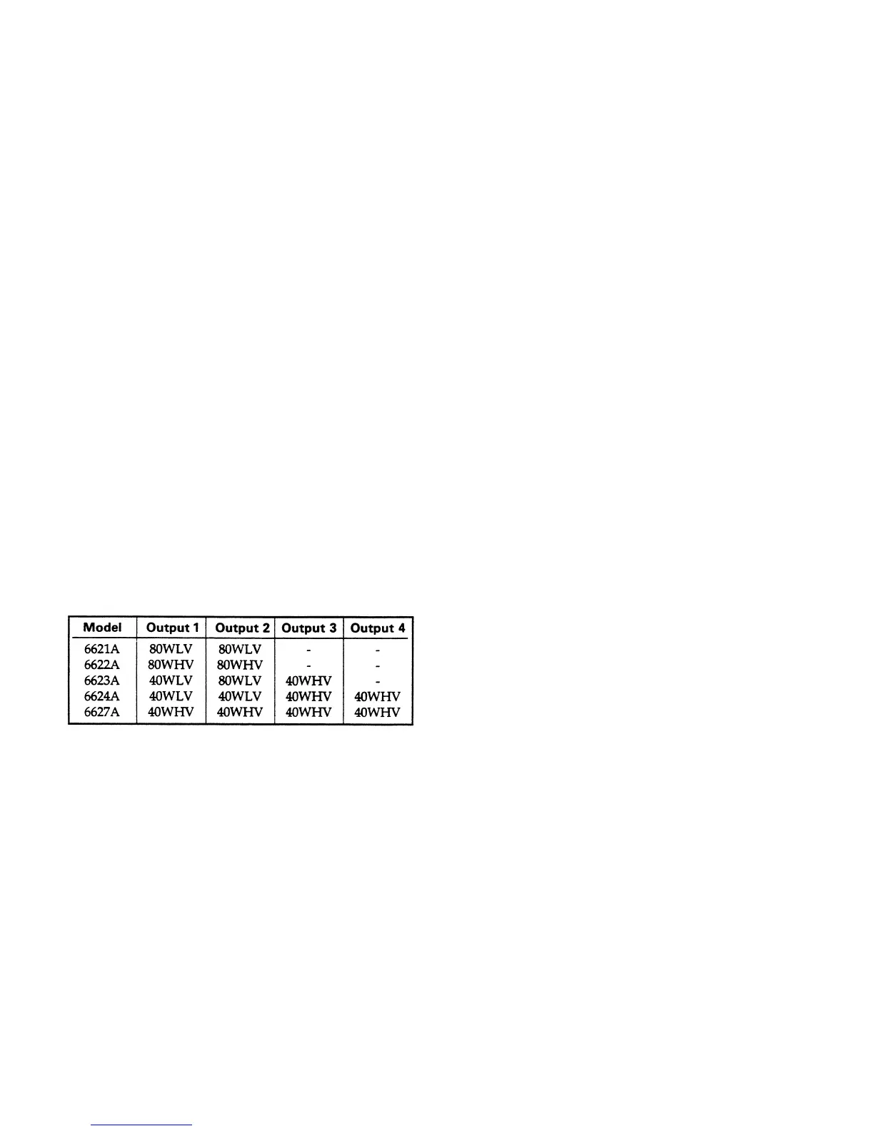
Figure 6-3, 6-4 and 6-5 illustrate the circuits on the 40 Watt
Low Voltage (40WLV), 40 Watt High Voltage (40WHV), 80
Watt Low Voltage (80WLV), and 80 Watt High Voltage
(80WHV) Output board types. The output board
configuration for each model is as follows:
This section contains functional schematic diagrams and
component location diagrams for the power supply.
The power supply circuits are shown on Figure 6-1 through
that illustrate the circuits functionally.
Sheet 2 - Bias, Turn-on, and Overvoltage circuits.
Sheet 3 - Control circuit, FET downprogrammer, Bleed and
Sense Protect circuits.
Sheet 4 - Power Mesh circuits.
6-5. The schematics consists of one or more foldout sheets
Figure 6-3 (Sheets 1 through 4) show the following circuits
and cover all 40W output board types. Differences between
the types are indicated on the schematic.
Sheet 1 - Secondary interface circuits.
Figure 6-4 (Sheets 1 through 4) are similar to Figure 6-3
and cover all 40W output board types. Differences between
the types are indicated on the schematic.
Figure 6-5 (Sheets 1 through 4) are similar to Figures 6-3
between the types are indicated on the schematic.
and 6-4, and cover all 80W output board types. Differences

 Loading...


