140 Chapter2
Making Adjustments
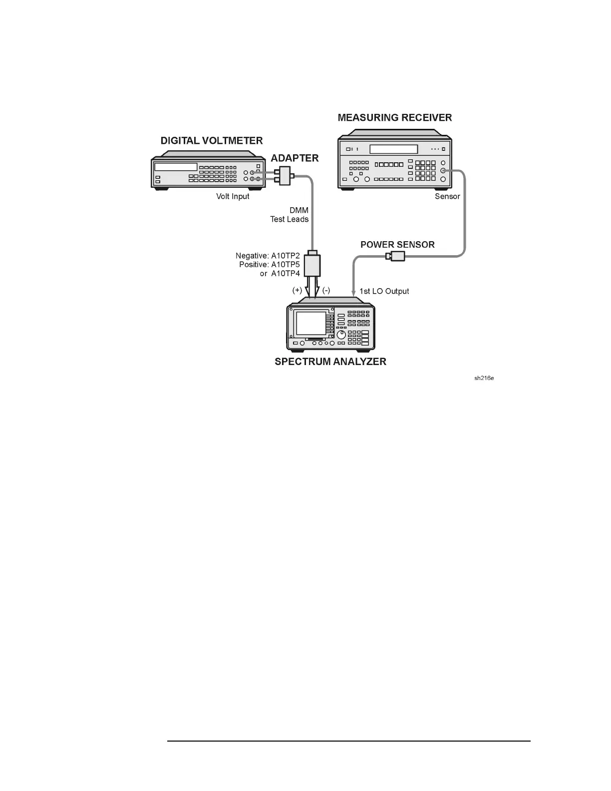
22. First LO Distribution Amplifier for Option 009 or 010
Figure 2-33 First LO Distribution Amplifier Adjustment Setup
4. Set the digital voltmeter controls as follows:
FUNCTION .............................................. DCVOLTS
RANGE ................................................................ 10 V
RESOLUTION .................................................... 1 mV
5. Set the analyzer
LINE switch to on.
6. Adjust A10R29 (GATE) for a digital voltmeter reading within 5 mV
of the GATE (gate bias) voltage printed on the RF section label.
7. Zero and calibrate the measuring receiver and power sensor in LOG
mode. (Power levels read in dBm.) Enter the power sensor's 5 GHz
cal factor into the measuring receiver.
8. Connect the power sensor to the analyzer LO OUTPUT.
9. On the analyzer, press
PRESET, SPAN, ZERO SPAN, FREQUENCY, 300,
MHz.
10.Connect the positive DMM test lead to A10TP4, LOS (LO sense).
11.Note the SENS (LO sense) voltage printed on the RF section label.
Adjust A10R25, LO AMP (LO power), until the DMM reads equal to
the SENS voltage printed on the RF section label.
 Loading...

