146 Chapter2
Making Adjustments
24. Tracking Oscillator for Option 010
Additional Equipment for Option 026
Cable, CAL comb
Adapter APC-3.5 (f) to APC-3.5 (f)
Adapter, Type N (f) to APC-3.5 (f)
Adapter, Type BNC (f) to SMA (m)
Procedure
Frequency Tracking Range Check
1. Connect a cable between the RF OUT 50 Ω and INPUT 50 Ω
connectors on the analyzer.
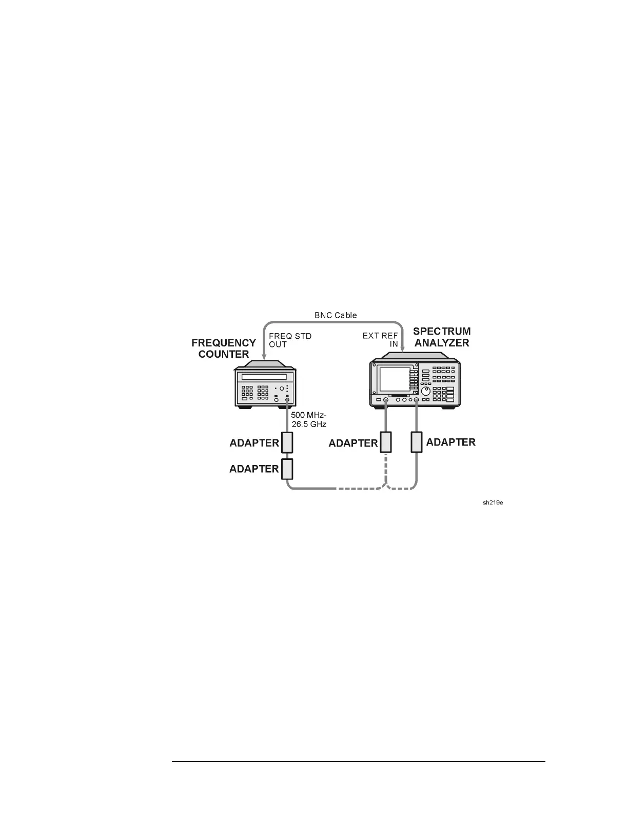
Figure 2-36 Frequency Tracking Range Setup
2. Remove the rear-panel jumper that is between the 10 MHz REF
OUTPUT and EXT REF IN jacks. Connect the frequency counter
FREQ STD OUT connector to the analyzer EXT REF IN connector
as shown in Figure 2-36.
3. Press
PRESET on the analyzer, then set the controls as follows:
CENTER FREQ ............................................ 500MHz
SPAN .....................................................................0Hz
4. On the analyzer, press the following key.
BW, 10, kHz
AUX CTRL, TRACK GEN, SRC PWR ON OFF (ON), 5, −dBm
5. On the analyzer press TRACKING PEAK. Wait for the PEAKING
message to disappear.
 Loading...

