Chapter 2 73
Making Adjustments
10. CAL YTF Adjustment Routine
Procedure
1. Perform the CAL FREQ routine as indicated in the “CAL FREQ
Adjustment Routine” in this chapter.
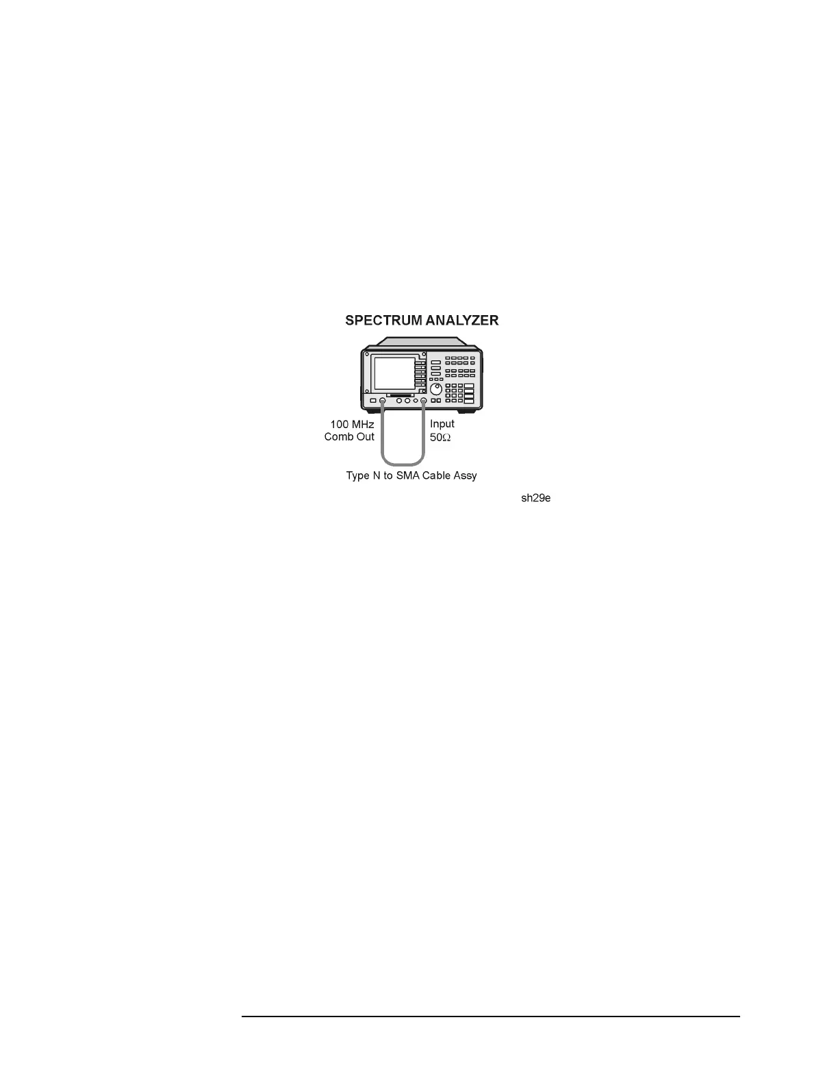
2. Connect the 100 MHz COMB OUT to INPUT 50 Ω using the YTF
CAL cable. Refer to Figure 2-15.
Model 8595E only: Connect the CAL OUT to the INPUT 50 Ω using a
BNC cable.
Figure 2-15 CAL YTF Adjustment Setup
3. Press the following keys.
PRESET
CAL, CAL YTF
The CAL YTF routine will take a few minutes to run. The message
“CAL: DONE” will be displayed when the routine has finished. The
internal adjustment data will be stored in working RAM.
If the message “LOST COMB SIGNAL” is displayed, perform the
Mixer Bias DAC Initialization procedure.
4. Press
CAL STORE to store the YTF correction data in nonvolatile
memory.
Mixer Bias DAC Initialization
If the message “LOST COMB SIGNAL” is displayed, the current mixer
bias DAC settings may not be adequate to ensure that a comb signal is
displayed. Initialization of the mixer bias DAC may be required.
Perform this procedure only if the “LOST COMB SIGNAL” message is
displayed while performing the
CAL YTF routine and the analyzer
firmware is version 3.1.90 or later.
 Loading...

