Chapter 7 Tutorial
Output Characteristics
138
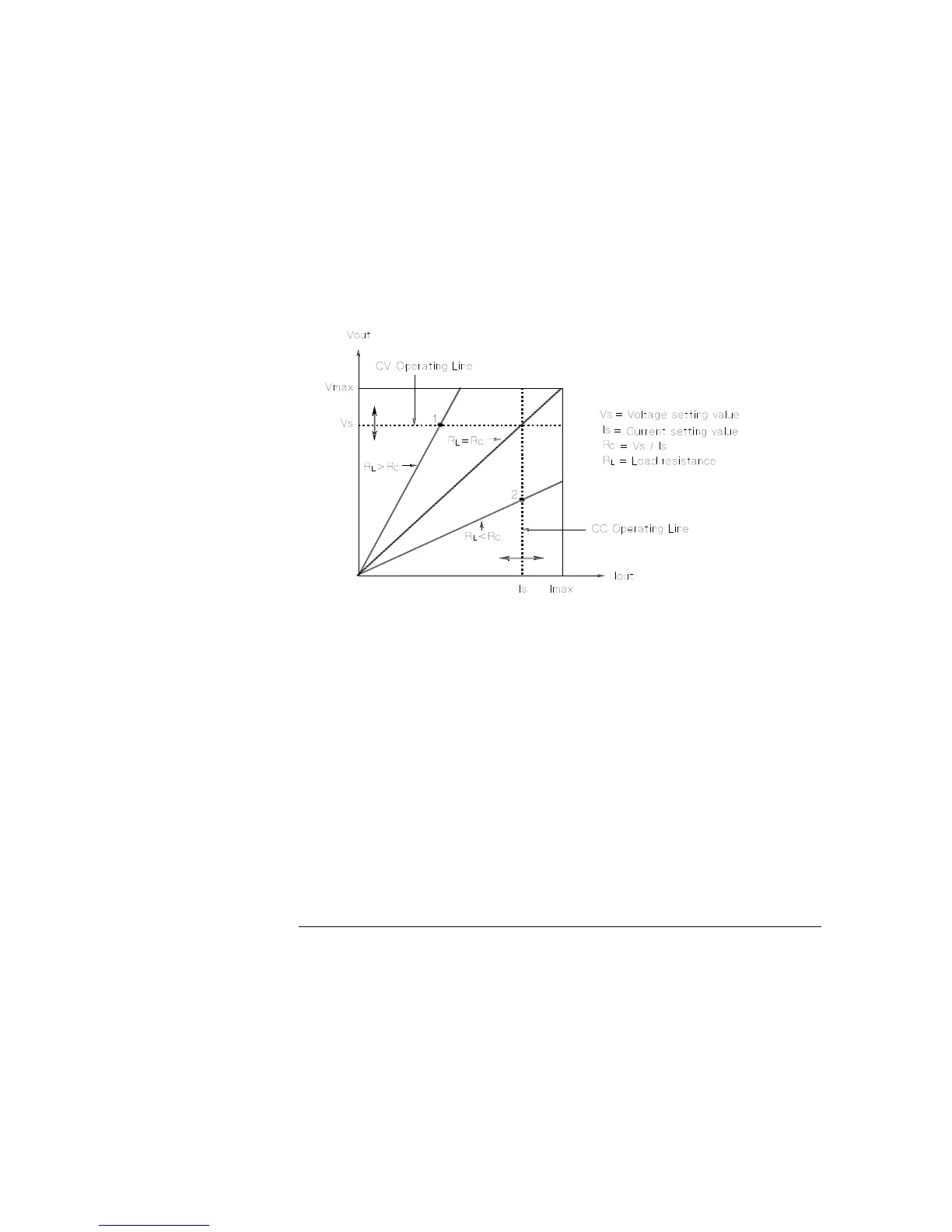
Figure 7-5 shows the operating modes of the output of the Agilent E3633A and Agilent
E3634A power supplies. The operating point of one supply will be either above or
below the line R
L
= R
C
. This line represents a load where the output voltage and the
output current are equal to the voltage and current setting. When the load R
L
is greater
than R
C
, the output voltage will dominate since the current will be less then the current
setting. The power supply is said to be in constant voltage mode. The load at point 1
has a relatively high resistance value (compared to R
C
), the output voltage is at the
voltage setting, and the output current is less than the current setting. In this case the
power supply is in the constant voltage mode and the current setting acts as a current
limit.
Figure 7-5. Output Characteristics
When the load R
L
is less than R
C
, the output current will dominate since the voltage
will be less than the set voltage. The power supply is said to be in constant current
mode. The load at point 2 has a relatively low resistance, the output voltage is less
than the voltage setting, the output current is at the current setting. The supply is in
constant current mode and the voltage setting acts as a voltage limit.