Chapter 2 51
Installation and Setup
Verifying the System Connections
Verifying the System Connections
Upon completion of the hardware setup and system configuration, you can verify
the system is prepared for calibration and making measurements.
CAUTION Before connecting a signal to the PSA, make sure the PSA can safely accept the
signal level provided. The signal level limits are marked next to the connectors on
the front panel.
The signal level measured by the PSA is not going to be the same level applied to
the input of the sensor module (N5532A/B); there is about a 6 dB loss through the
sensor module.
Step 1. Make sure you have applied power to the UUT. Wait until the equipment warm-up
complete.
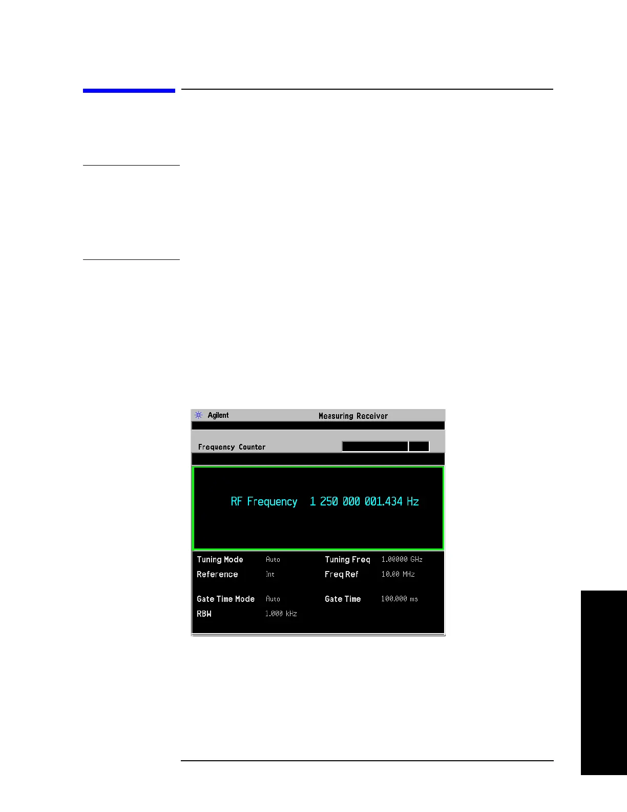
Step 2. Adjust the UUT to output an RF signal, like 1.25 GHz at 0 dBm.
Step 3. Press
MODE and select Measuring Receiver.
Step 4. Press
Preset, then the PSA will automatically make a Frequency Counter
measurement as shown.
Figure 2-4 Measuring Receiver Default Measurement (Frequency Counter)
 Loading...


