Chapter 5 293
Concepts
Analog Modulation Concepts
The range of modulation indexes for AM measurements by the Measuring
Receiver is essentially 0 to 100%. There are, however, types of modulation that
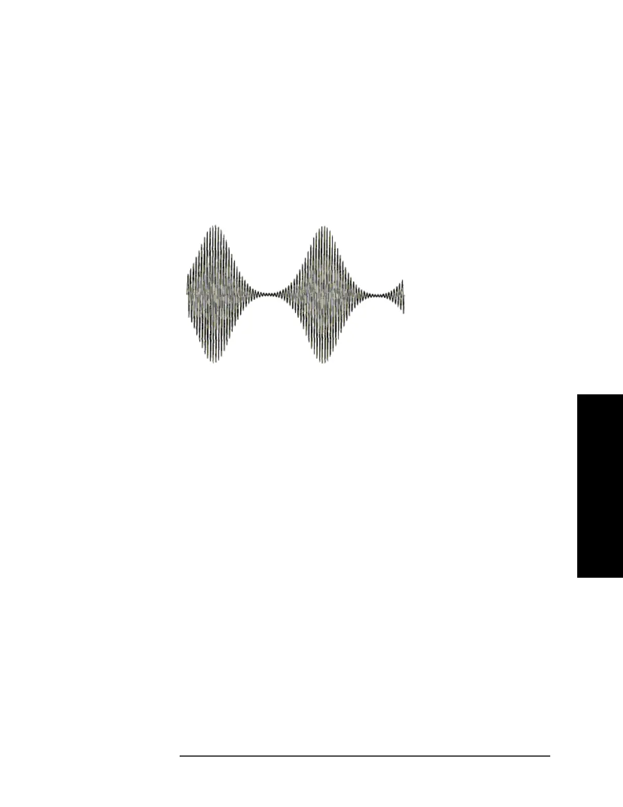
produce modulation indexes greater than 100%. An example of such is
suppressed-carrier AM. The Measuring Receiver is not intended for measuring
such signals. Nevertheless, there are cases, when the Measuring Receiver will
display a modulation index that exceeds 100%. This can occur, for example, on an
asymmetrical waveform where a narrow peak is greater than the average carrier
level. This is illustrated in Figure 5-7 on page 293.
Figure 5-7 AM with Modulation Exceeding 100% as Measured by the Peak+ Detector
Phase (Exponential) Modulation
Phase (Exponential, or angular) modulation is the generic name given to
modulation in which the frequency or phase of the carrier is varied. Frequency and
phase modulation are very closely related. In fact, it is impossible to tell whether
the signal was produced by a frequency modulator or phase modulator by
analyzing the received signal unless specific information about the baseband signal
is given.
It is certainly true to say that a signal is frequency modulated when the modulation
is generated by a frequency modulator. A varactor diode across the tank circuit of
an LC oscillator will produce FM when the varactor bias is varied. (It is assumed
that the carrier is on the slope of the filter and that the filter is driven from a
well-buffered carrier source. This modulator simultaneously produces AM.)
The signal from both modulators will show readings on the Measuring Receiver
when in both the FM and ΦM measurement modes. When in FM, the quantity
being measured is the peak frequency deviation, which is the maximum frequency
excursion from the average carrier frequency. When measuring ΦM, the peak
phase deviation is measured, which is the maximum phase excursion from the
average carrier phase. Phase and frequency have the relationship that phase is the
integral of the frequency or frequency is the derivative of the phase.
This relationship is most easily visualized by some examples. Look at Figure 5-8
on page 294. The first baseband signal shown is a square wave. The three
waveforms under it are the result of applying this signal to an FM, ΦM, and AM
modulator respectively. (The AM waveform is included only for reference.) It is
 Loading...


