Chapter 2 45
Installation and Setup
Setting up the System
Step 2. Set up the N5531S Measuring Receiver system by correctly connecting the PSA,
Power Meter, Sensor Module and Unit Under Test (UUT). See Figure 2-1,
“Hardware Setup Block Diagram,” on page 44.
CAUTION While connecting the sensor module to the UUT, make sure you follow the
instructions below:
1. Before connecting a signal to the sensor module, make sure the sensor module
can safely accept the signal level provided. See Sensor Module Users Guide to
view the signal level limits.
2. Turn only the connector sleeve portion of the sensor module. Damage can
occur if torque is applied to the sensor module body.
3. If possible, ensure the sensor rests flush against a desktop or other support. This
helps prevent mechanical damage to the sensor and UUT RF OUT connector.
See Figure 2-3, “Connecting the Sensor Module to the UUT,” on page 45.
4. Maximum torque at the connector should NOT exceed 12 in-pound (135 Ncm)
for the Type-N connector or 8 in-pound (90 Ncm) for the 3.5-mm or 2.4 mm
connector to avoid damage to the connector.
Step 3. Connect power cords to the PSA, Power Meter and UUT.
Figure 2-1, “Hardware Setup Block Diagram,” on page 44 illustrates the system
hardware after being set up and connected with UUT and figures below illustrate
some examples of system component and connections.
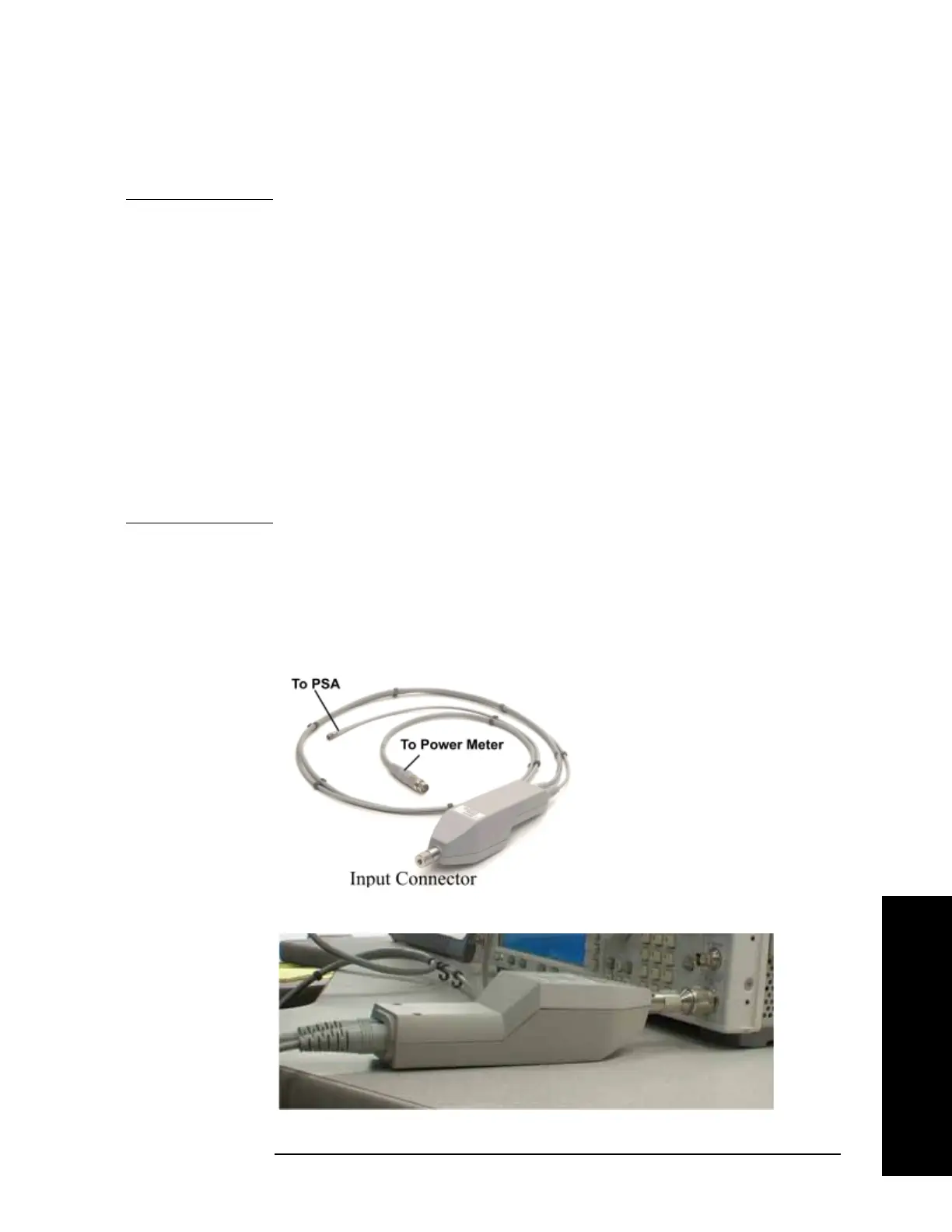
Figure 2-2 N5532A/B Sensor Module
Figure 2-3 Connecting the Sensor Module to the UUT
 Loading...


