9-8 EB AT-RP-4GU EN
Service
Fig. 9-12
15
16
40
05
Fig. 9-13
01
Fig. 9-14
40
40
50
40° - 45°
− With pistons completely closed (0° position) as per Fig.
9-15, referring to the axis of the body, the rotation ob-
tained must be:
– about over 0° up to 5°, for models AT051U to
AT801U
– strictly about over 0° up to 0.5° for model AT045U.
− With pistons completely closed (0° position) as per Fig.
9-15 the dimension “A“ must be the same on both sides
Fig. 9-15
90° position 0° position
01 4040
40
40
01
5°
A
A
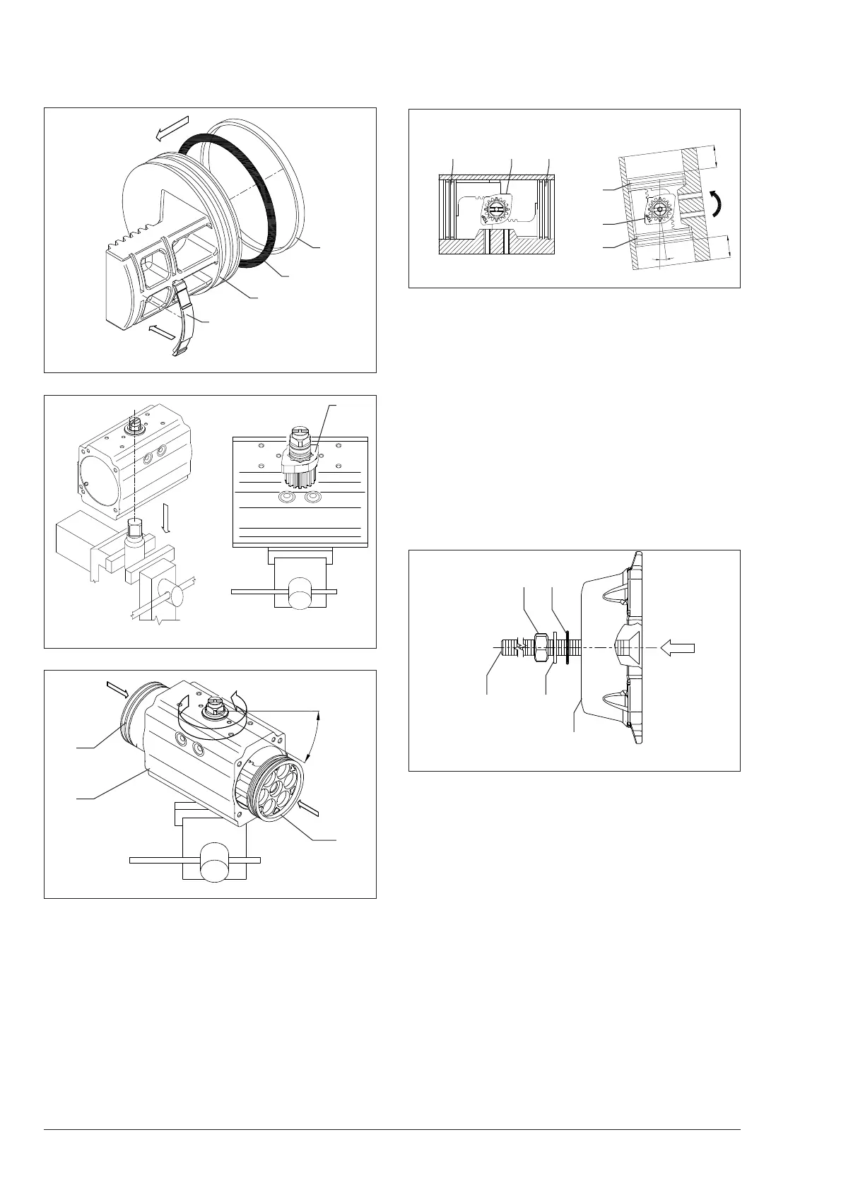
9.5.3 End caps reassembly
Assemble one end cap (30/30R) at a time.
− In case of actuator with extra travel stop adjustment:
– fasten the stop screws (221G/222G) into the end caps
(30) aligning the head of the screw to the end cap sur-
face as shown in Fig. 9-16.
– lubricate and place the o-rings (11R),
– place the washer (03R) and fasten partially the nuts
(04R).
Î Refer to the data sheet [T.D.S. 2.1.5.1.1] for extra travel
stop adjustment components.
Fig. 9-16
11R04R
221G
222G
03R
30R
− Place the end caps o-ring (14) into the groove as shown in
Fig. 9-17 making sure that the o-ring is stable in its
housing.
− Lubricate again the internal surface of the body (50).
− Place the actuator in vertical position.
− In case of spring return actuator, place the correct quantity
of spring cartridges in the correct position as indicated in
Table 9-4, Table 9-5, Fig. 9-18 and Fig. 9-19 depending
on the actuator model.