EB AT-RP-4GU EN 9-9
Service
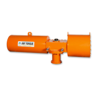
Fig. 9-17
14
30
30R
Table 9-4
SPRING TYPE FOR MODELS AT045U
Spring set Side B Side A
S1-1 1 (green) 1 (green)
S1-2 1 (green) 2 (red)
S2-2 2 (red) 2 (red)
S2-3 2 (red) 3 (black)
S3-3 3 (black) 3 (black)
Table 9-5
SPRING TYPE FOR MODELS AT051U
Spring set Side B Side A
Internal External Internal External
S1 1 (green) / / 2 (black)
S2 / 2 (black) / 2 (black)
S3 / 2 (black) / 3 (red)
S4 / 3 (red) / 3 (red)
S5 / 3 (red) 1 (green) 2 (black)
S6 1 (green) 2 (black) 1 (green) 2 (black)
S7 1 (green) 2 (black) 1 (green) 3 (red)
S8 1 (green) 3 (red) 1 (green) 3 (red)
Fig. 9-18
17
17.3
17.1
17.2
AT045U and AT051U from AT101U to AT801U
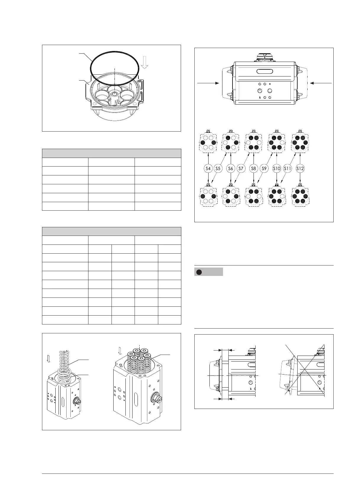
Fig. 9-19
Side A
Side A
Side B
Side B
models AT101U to AT801U
− Place the end cap (30/30R).
− Fix the end cap (30/30R) fastening partially the cap
screws (13) 1 turn at a time following the sequence indi-
cated in Fig 9-21.
Risk of components damage due to incorrect assembly.
During reassembling the end caps can be damaged due to
uneven force generated by compressed springs.
Î Assemble the end caps as shown in Fig. 9-20 keeping a
constant distance (A = B) between the actuator body and
the end cap interface.
Î Observe the specied sequence shown in Fig. 9-21.
Fig. 9-20
B
A
A = B
− Complete the fastening of the cap screws (13) tightening 1
turn at a time for each screw in th sequence shown in Fig.
9-21.
Î Refer to the section 15.2 ‘Tightening torques‘. (Table 15.1)
NOTICE
!