9-10 EB AT-RP-4GU EN
Service
Fig. 9-21
3
2
4
1
1
2
5
3
4
6
1
7
2
5
3 8
4
6
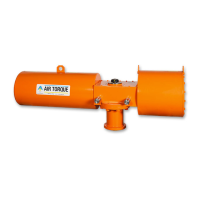
TOTAL QUANTITY OF
CAP SCREWS (13)
PER ACTUATOR:
− 8
− 12
− 16
SEQUENCE OF
ASSEMBLY:
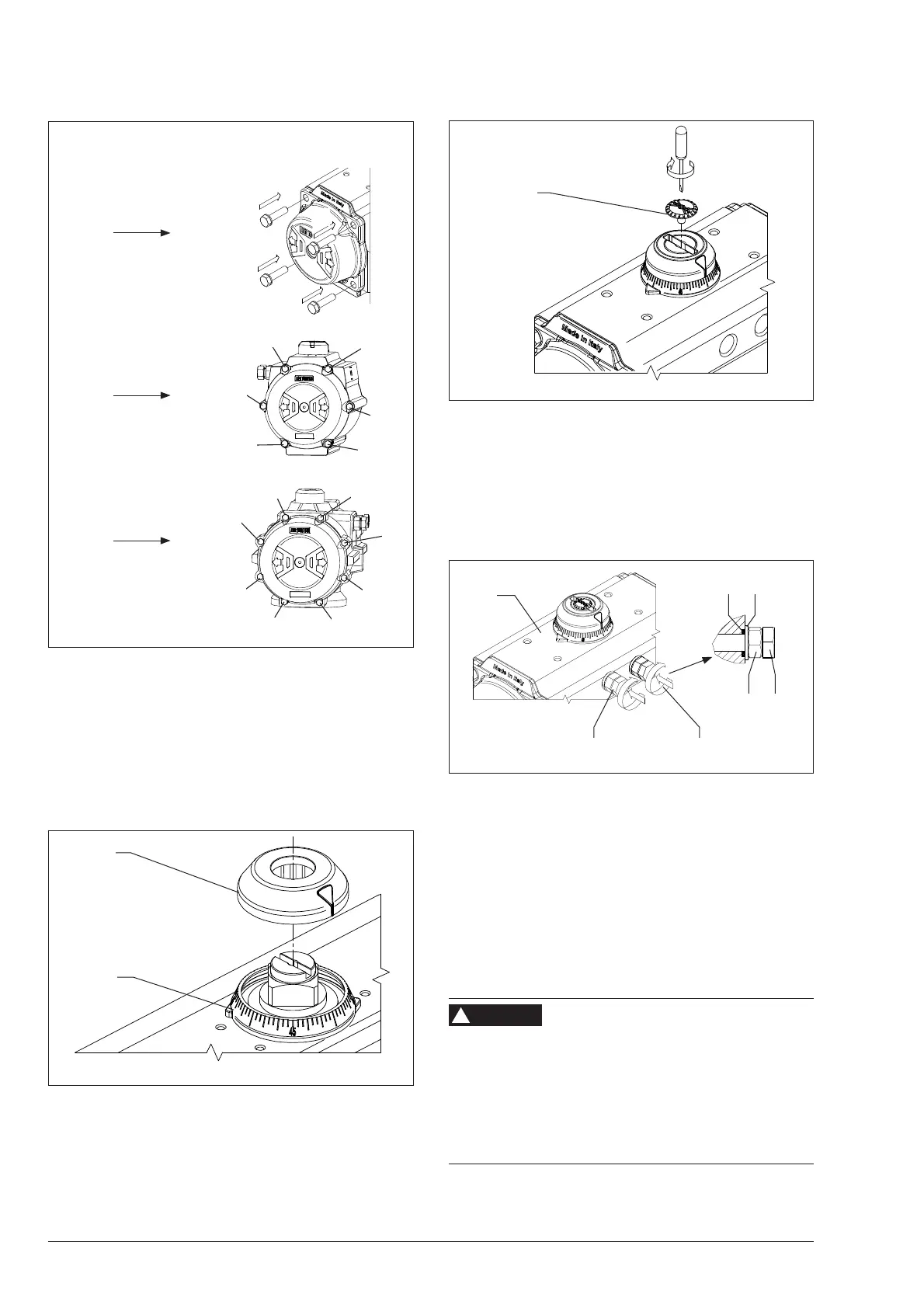
9.5.4 Position indicator reassembly
Refer to Fig. 9-1, Fig. 9-22 and Fig. 9-23.
− Fix the graduated ring (19.0) into the body, if any.
− Place the indicator (19/19.1) referring to the correct actu-
ator position.
− Fasten the indicator screw (39), if any. (Fig. 9-23)
Fig. 9-22
19
19.1
19.0
39
Fig. 9-23
9.5.5 Stop cap screws reassembly
Refer to Fig. 9-1 and Fig. 9-24.
− Insert onto both stop screws (02), the nut (04), the washer
(03) and the o-ring (11).
− Place the stop cap screws (02) into the body (50).
Fig. 9-24
50
LEFT RIGHT
0204
0311
9.5.6 Stroke adjustment
Refer to Fig. 9-1 and Fig. 9-24.
Close position
− With the actuator in close position (0° position) referring
to Fig. 9-15 for pistons position, screw or unscrew the
right stop screw (02) 1 turn at a time until the desired stop
position is achieved. In case of spring return actuator, a
pneumatic supply may be necessesary.
Risk of personal injury due to pneumatic supply.
Stop screws are not still properly tightened. Any pneumatic
supply can eject the stop screws out from the actuator body.
Î Before starting pressurizing the actuator, make sure the
stop screws are screwed at least for a legth equal to the
screw diameter. Refer to the ‘Tightening torques‘ (Table
15.3) for the screw dimensions.
WARNING
!