AHLD Series | Heatless Regenerative Desiccant Air Dryer
20
AIRCEL PROGRAMMABLE CONTROLLER (APC)
Dryer Operations
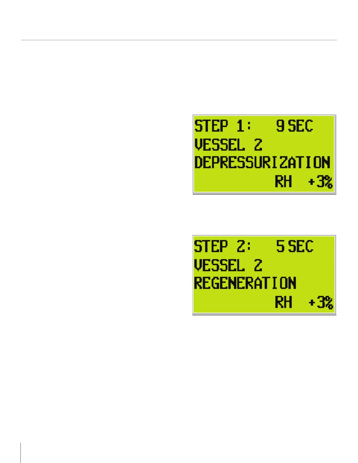
STEP ONE: Select Vessel 2 Depressurizing (0 - 5 seconds)
Vessel 2 (T2) purge exhaust pilot solenoid valve is energized,
supplying control air to slowly open the purge exhaust valve
(V4), depressurizing vessel 2 (T2).
Simultaneously, the inlet valves V1 and V2 shift positions with
a pneumatic signal from vessel 2 (T2) purge exhaust pilot
solenoid valve to the inlet tower selector pneumatic pilot valve.
This action supplies a pneumatic signal to the inlet valves to
open valve (V1) and close valve (V2), directing the inlet air to
vessel 1 (T1) to dry the air.
The air flows up through the desiccant bed and exits outlet
valve (V5) to the outlet particulate filter. The air then moves
down the line, to the customer dry process air system.
STEP TWO: Vessel 2 Regenerating (6 - 240 seconds)
Vessel 2 (T2) is regenerating, Vessel 2 (T2) purge exhaust valve
(V4) is still open, Vessel 1 (T1) is drying the inlet air.
A small portion of dry outlet air from Vessel 1 (T1) (15% average
based on standard design capacity of 100 psig, 100°F ambient
air and PDP of -40°F) is taken through a small orifice in the
outlet line and used to regenerate the desiccant bed in Vessel 2
(T2) until 240 seconds has been reached.
The timer on this step counts to 240 seconds (4-minutes).
A warning sign will flash in the upper right hand portion of the
screen and a red LED alarm light will flash on the PLC display
for any alarm. To view alarms, press the left arrow once from
the main screen.
The screen also displays the relative humidity reading and dew
point (optional).