Tools & Materials
Fairing (MANDATORY) (High-Performance Fairing recommended)
Safety goggles
Dust mask
Electric drill
Drill bit: 3mm or 1/8"
Hole saw: 51mm or 2"
Sandpaper
Mild household detergent or weak solvent (such as alcohol)
Angle finder or digital level
Band saw
Rasp or power tool
Marine sealant (suitable for below waterline)
Slip-joint pliers
Grommet(s) (some installations)
Cable ties
Water-based anti-fouling paint (mandatory in salt water)
Installation in a cored fiberglass hull (see page 4):
Hole saw for hull interior: 60mm or 2-3/8"
Cylinder, wax, tape, and casting epoxy
Mounting Location
Guidelines
CAUTION: Do not mount near water intake or discharge openings
or behind strakes, fittings, or hull irregularities that will disturb the
water flow.
• The water flowing under the hull must be smooth with a
minimum of bubbles and turbulence (especially at high speeds).
• The sensor must be continuously immersed in water.
• The transducer beam must be unobstructed by the keel or
propeller shaft(s).
• Choose a location away from interference caused by power and
radiation sources such as: the propeller(s) and shaft(s), other
machinery, other echosounders, and other cables. The lower
the noise level, the higher the echosounder gain setting that
can be used.
• Choose a location with a minimum deadrise angle.
• Choose an accessible spot inside the vessel with adequate
headroom for the height of the housing, tightening the nut(s),
and installing any insert.
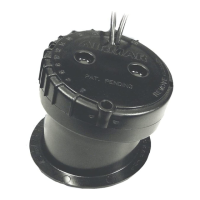
Model
Min. with fairing
B744V 255mm (10")
B744VL 381mm (15")
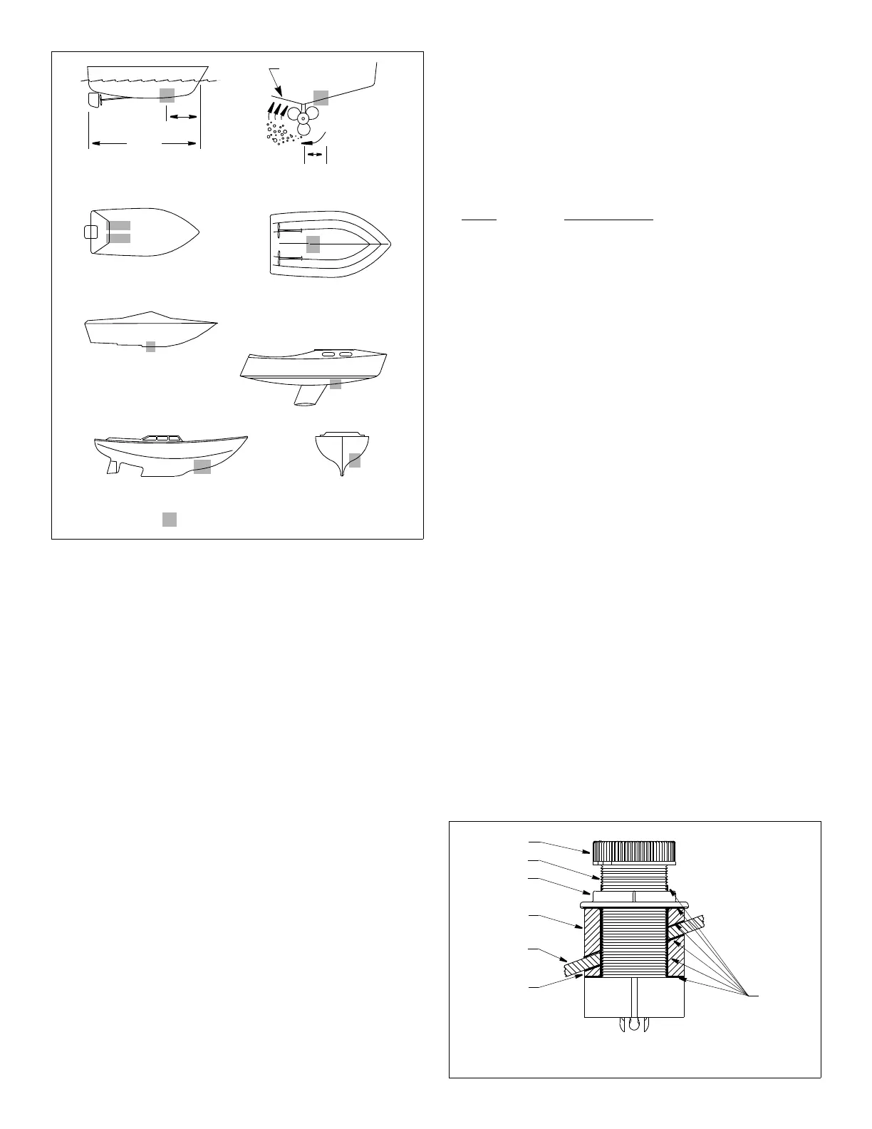
Boat Types (see Figure 1)
• Displacement hull powerboat—Locate 1/3 of the way back
along the LWL and 150–300mm (6–12") off the centerline. The
starboard side of the hull where the propeller blades are moving
downward is preferred.
• Planing hull powerboat—Mount well aft near the centerline and
well inboard of the first set of lifting strakes to ensure that it is in
contact with the water at high speeds. The starboard side of the
hull where the propeller blades are moving downward is preferred.
Outboard and I/O—Mount forward and to the side of the
engine(s).
Inboard—Mount well ahead of the propeller(s) and shaft(s).
Stepped hull—Mount just ahead of the first step.
Boats capable of speeds above 25kn (29MPH)—Review
sensor location and operating results of similar boats before
proceeding.
• Fin keel sailboats—Mount to the side of the centerline and
forward of the fin keel 300–600mm (1–2').
• Full keel sailboats—Locate amidships and away from the keel
at the point of minimum deadrise angle.
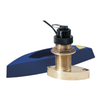
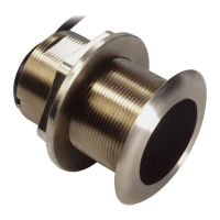
Installation: B744V/VL with Standard Fairing Only
WARNING: B744V/VL—These instructions are for installing a
standard fairing only. If you are installing the B744V/VL with a
High-Performance Fairing, you must follow the installation
instructions that come with the fairing.
WARNING: B765LH/LM must be installed with a High-
Performance Fairing only! You must follow the installation
instructions that come with the fairing.
2
Figure 1. Best location for the sensor
inboard
pressure waves
1/3
full keel sailboat
displacement hull
(6–12")
fin keel sailboat
150–300mm
LWL
(Load Waterline Length)
stepped hull
outboard and I/O
planing hulls
Copyright © 2005 - 2010 Airmar Technology Corp.
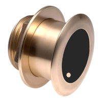
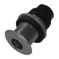
marine
stem
hull nut
backing
hull
Standard
Figure 2. Drilling and bedding (B744V shown)
cap nut
block
Copyright © 2005 2010 Airmar Technology Corp.
Fairing
sensor housing
sealant