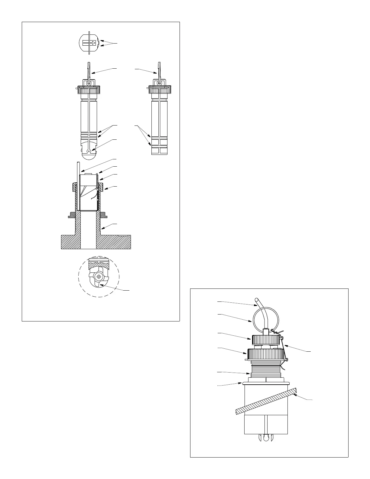
Figure 6. Paddlewheel insert, blanking plug,
BOW
►
flat side of
paddlewheel
paddlewheel
cap nut
paddlewheel
top view of
housing and
blade faces
paddlewheel
insert
insert
valve assembly
housing
and valve assembly (B744V shown)
notches
key (2)
valve
assembly
insert detail
cable
blanking
plug
direction of
arrow on top
of insert
(toward bow)
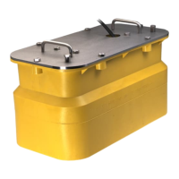
Figure 7. Installation (B744V shown)
pull ring
hull
Standard
sensor
safety wire
cap nut
hull nut
backing
stem
cable
block
B744V/VL: Installing the Paddlewheel Insert
1. After the sealant cures, inspect the O-rings on the paddlewheel
insert (replace if necessary) and lubricate them with the silicone
lubricant supplied (see Figure 6). The O-rings must be intact and
well lubricated to make a watertight seal.
2. Slide the paddlewheel insert into the housing with the arrow on
the top pointing forward toward the bow. Seat it into place using
a twisting motion until the keys fit into the notches. (The insert
fits one way only.) Be careful not to rotate the outer housing and
disturb the sealant. Screw the insert nut in place and hand-
tighten only. Do not over tighten.
3. Attach the safety wire to prevent the insert from backing out in
the unlikely event that the cap nut and/or insert nut fails or is
screwed on incorrectly. Wrap one end of the safety wire tightly
around the stem of the housing and twist it together with the long
end (see Figure 7). Keeping the wire taut throughout, lead the
wire straight up and through one eye in the CAP nut. Thread the
wire through the eye a second time. Lead the wire in a
counterclockwise direction and thread it through the eye in the
insert nut. Thread the wire through that eye a second time. Loop
the wire through the pull ring and twist the wire securely to itself.
Installation in a Cored Fiberglass Hull
The core (wood or foam) must be cut and sealed carefully. The
core must be protected from water seepage, and the hull must be
reinforced to prevent it from crushing under the hull nut, allowing
the housing to become loose.
CAUTION: Completely seal the hull to prevent water seepage into
the core.
1. Drill a 3mm or 1/8" pilot hole perpendicular to the waterline from
inside the hull (see Figure 8). If there is a rib, strut, or other hull
irregularity near the selected mounting location, drill from the
outside. (If the hole is drilled in the wrong location, drill a second
hole in a better location. Apply masking tape to the outside of the
hull over the incorrect hole and fill it with epoxy.)
2. Using the 51mm or 2" hole saw, cut a hole from outside the hull
through the outer skin only. Be sure to hold the drill plumb, so
the hole will be perpendicular to the water surface.
3. The optimal interior hole diameter is affected by the hull’s
thickness and deadrise angle. It must be large enough in
diameter to allow the core to be completely sealed.
Using the 60mm or 2-3/8" hole saw, cut through the inner skin
and most of the core from inside the hull keeping the drill
perpendicular to the hull. The core material can be very soft.
Apply only light pressure to the hole saw after cutting through the
inner skin to avoid accidentally cutting the outer skin.
4. Remove the plug of core material so the inside of the outer skin
and inner core of the hull is fully exposed. Sand and clean the
inner skin, core, and the outer skin around the hole.
5. Coat a hollow or solid cylinder of the correct diameter with wax
and tape it in place. Fill the gap between the cylinder and hull
with casting epoxy. After the epoxy has set, remove the cylinder.
4
Copyright © 2005 Airmar Technology Corp.
Copyright © 2005 Airmar Technology Corp.
insert nut
NOTE: Do not remove
the CAP nut to service
the paddlewheel insert.
The valve assembly
will come out.
pull ring
O-rings
shaft
Fairing