Hole Drilling
Cored Fiberglass Hull—Follow separate instructions on page 4.
1. Drill a 3mm or 1/8" pilot hole perpendicular to the waterline from
inside the hull (see Figure 2). If there is a rib, strut, or other hull
irregularity near the selected mounting location, drill from the outside.
2. Using the 51mm or 2" hole saw, cut a hole from outside the hull.
Be sure to hold the drill plumb, so the hole will be perpendicular
to the water surface.
3. Sand and clean the area around the hole, inside and outside, to
ensure that the sealant will adhere properly to the hull. If there is
any petroleum residue inside the hull, remove it with either mild
household detergent or a weak solvent (alcohol) before sanding.
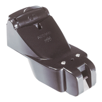
Cutting the Standard Fairing
CAUTION: The button on the fairing points forward toward the
bow. Be sure to orient the fairing on the band saw so the angle cut
matches the intended side of the hull and not the mirror image.
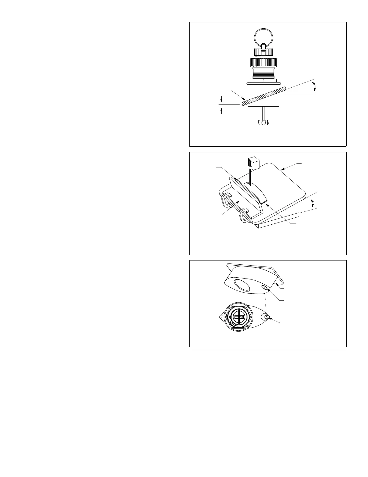
1. Measure the deadrise angle of the hull at the selected location
using an angle finder or a digital level (see Figure 3).
2. Tilt the band saw table to the measured angle and secure the
cutting fence (see Figure 4).
3. Place the Standard Fairing on the table, so the cutting guide
rests against the fence. The button will point toward you for
installation on the starboard side and away from you for
installation on the port side of the boat (see Figure 5).
4. Adjust the cutting fence so the fairing will be cut in about two
equal parts. The section that will become the fairing must be
between 6–12mm (1/4–1/2") at its thinnest dimension (see
Figure 3).
5. Recheck steps 1 through 4. Then cut the fairing.
6. Shape the fairing to the hull as precisely as possible with a rasp
or power tool.
7. Use the remaining section of the fairing with the cutting guide
for the backing block.
Bedding
CAUTION: Be sure all surfaces to be bedded are clean and dry.
1. Remove the hull nut (see Figure 2).
2. Apply a 2mm (1/16") thick layer of marine sealant over the
surface of the sensor housing that will contact the fairing and up
the stem. The sealant must extend 6mm (1/4") higher than the
combined thickness of the fairing, hull, backing block, and hull
nut. This will ensure there is marine sealant in the threads to seal
the hull and hold the hull nut securely in place.
3. Apply a 2mm (1/16") thick layer of marine sealant to the surface
of the:
• Fairing that will contact the hull
• Backing block that will contact the hull interior
• Hull nut that will contact the backing block
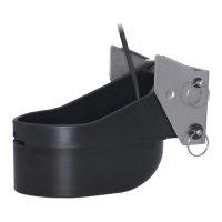
4. Thread the cable through the fairing. Slide the fairing onto the
stem and mate the button with the recess in the sensor’s
housing (see Figure 5).
Installing the Housing
CAUTION: B744V/VL—Be careful to avoid cross threading the
CAP nut.
1. From outside the hull, thread the cable through the mounting hole.
Then push the stem of the sensor housing through the hole using
a twisting motion to squeeze out excess sealant. Be sure the
3
Figure 4. Cutting the Standard Fairing
button
Figure 5. Airmar Standard Fairing (B744V shown)
BOW ►
6–12mm (1/4–1/2")
backing
hull
Standard
sensor
deadrise
fairing thickness
angle
slope of hull
parallel to
waterline
block
Figure 3. Deadrise angle and fairing thickness (B744V shown)
at thinnest point
recess in
sensor housing
cutting guide
Copyright © 2005 - 2010 Airmar Technology Corp.
Copyright © 2005 - 2010 Airmar Technology Corp.
Copyright © 2005 - 2010 Airmar Technology Corp.
standard
Fairing
cutting
guide
band saw
table
deadrise
angle
button end
for installation
on starboard
fence
side of the hull
button on the fairing is mated with the recess in the sensor and it
is pointing forward toward the bow (see Figure 5). Take care to
align the assembly parallel to the centerline of the boat.
2. From inside the hull, slide the backing block onto the stem and
seat it firmly against the hull, being sure the pointed end faces
forward toward the bow (see Figure 2). Screw the hull nut in
place. Tighten it with slip-joint pliers.
Cored fiberglass hull—Do not over tighten, crushing the hull.
Wood hull—Allow the wood to swell before tightening.
3. B744V/VL—Being sure the valve assembly is seated firmly
within the housing, carefully screw the CAP nut in place. Hand-
tighten only. Do not over tighten.
4. Remove any excess sealant on the outside of the fairing and
the hull to ensure smooth water flow under the sensor.
Aft View
fairing