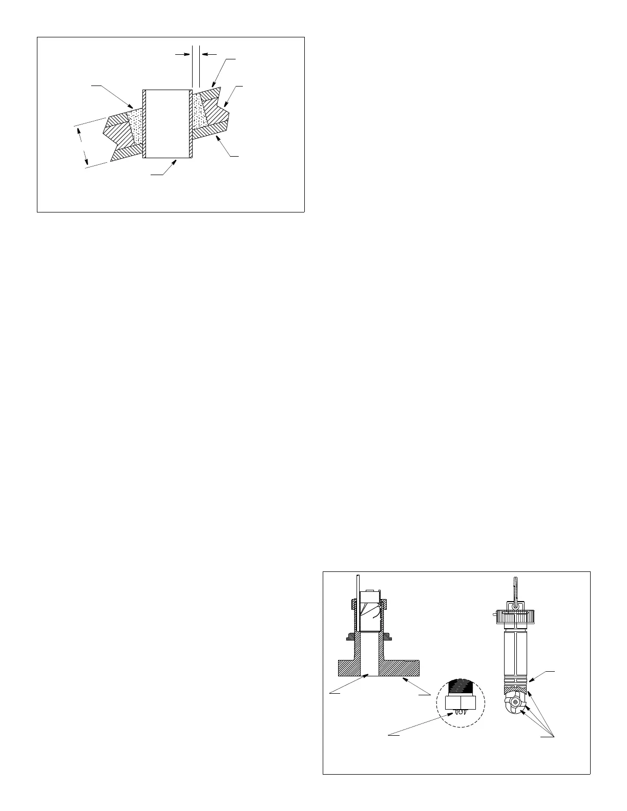
hull’s outer skin to
hull
outer skin
solid or hollow
cylinder
pour in
casting
epoxy
core
inner skin
Figure 8. Preparing a cored fiberglass hull
Dimension equal to
the thickness of the
ensure adequate
clearance
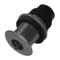
Figure 9. Anti-fouling paint (B744V shown)
Paint outside wall below the lower O-ring
including exposed end, paddlewheel cavity and paddlewheel
Paint exposed housing
lower
O-ring
and bore up 30 mm (1-1/4")
paddlewheel
insert
housing
detail
6. Sand and clean the area around the hole, inside and outside, to
ensure that the sealant will adhere properly to the hull. If there is
any petroleum residue inside the hull, remove it with either mild
household detergent or a weak solvent (alcohol) before sanding.
7. Proceed with “Cutting the Standard Fairing” on page 3.
Cable Routing & Connecting
CAUTION: If the sensor came with a connector, do not remove it
to ease cable routing. If the cable must be cut and spliced, use
Airmar’s splash-proof Junction Box No. 33-035 and follow the
instructions supplied. Removing the waterproof connector or
cutting the cable, except when using a water-tight junction box,
will void the sensor warranty.
1. Route the cable to the instrument, being careful not to tear the
cable jacket when passing it through the bulkhead(s) and other
parts of the boat. Use grommets to prevent chafing. To reduce
electrical interference, separate the sensor cable from other
electrical wiring and the engine. Coil any excess cable and
secure it in place using cable ties to prevent damage.
2. Refer to the echosounder owner’s manual to connect the
sensor to the instrument.
Check for Leaks
When the boat is placed in the water, immediately check around
the sensor for leaks. Note that very small leaks may not be readily
observed. Do not leave the boat in the water for more than 3
hours before checking it again. If there is a small leak, there may
be considerable bilge water accumulation after 24 hours. If a leak
is observed, repeat “Bedding” and “Installing” immediately (see
page 3).
Operation & Maintenance
Anti-fouling Paint
Surfaces exposed to salt water must be coated with anti-fouling
paint. Use water-based anti-fouling paint only. Never use ketone-
based paint since ketones can attack many plastics possibly
damaging the transducer. Reapply paint every 6 months or at the
beginning of each boating season.
B744V/VL: Additional Anti-fouling Paint
Paint the following surfaces (see Figure 9).
• Exposed areas of the housing including the transducer’s face
• Bore of the housing up 30mm (1-1/4")
• Outside wall of the paddlewheel insert below the lower O-ring
• Paddlewheel cavity
• Paddlewheel
• Blanking plug below the lower O-ring including the exposed end
Cleaning the Sensor
Aquatic growth can accumulate rapidly on the sensor’s surface,
reducing its performance within weeks. Clean the surface with
mild household detergent and a Scotch-Brite® scour pad.
B744V/VL—If fouling on the insert is severe, push out the
paddlewheel shaft using a spare shaft or a 4-D finish nail with a
flattened point. Then lightly wet sand the paddlewheel with fine
grade wet/dry paper.
B744V/VL: How the Valve Works
WARNING: The valve is not a watertight seal!
Always install the paddlewheel insert or the blanking plug secured
with the insert nut and safety wire for a watertight seal.
The multisensor incorporates a self-closing valve which minimizes
the flow of water into the vessel when the paddlewheel insert is
removed (see Figure 6). The curved flap valve is activated by both
a spring and water pressure. Water pushes the flap valve upward
to block the opening, so there is no gush of water into the boat.
B744V/VL: Using the Blanking Plug
To protect the paddlewheel, use the blanking plug:
• When the boat will be kept in salt water for more than a week.
• When the boat will be removed from the water.
• When aquatic growth buildup on the paddlewheel is suspected
due to inaccurate readings from the instrument.
1. On the blanking plug, inspect the O-rings (replace if necessary)
and lubricate them with silicone lubricant or petroleum jelly
(Vaseline®) (see Figure 6). The O-rings must be intact and well
lubricated to make a watertight seal.
2. Remove the paddlewheel insert from the housing by removing
the safety wire from the pull ring and the insert nut (see
Figure 7). Unscrew the insert nut. Do not remove the CAP nut,
as the valve assembly will come out.
3. Grasp the pull ring and remove the paddlewheel insert with a
slow pulling motion.
NOTE: In the unlikely event that the paddlewheel insert cannot
be removed, see “Servicing the Valve Assembly” on page 6.
4. Slide the blanking plug into the housing. Seat it into place with a
pushing twisting motion until the keys fit into the notches (see
Figure 6). Screw the insert nut in place and hand-tighten only.
Do not over tighten.
5. Reattach the safety wire (see Figure 7).
5
Copyright © 2005 Airmar Technology Corp.
Copyright © 2005 Airmar Technology Corp.
 Loading...