AS-D+—AS-P Series Instruction Manual 17
AirSep Corporation
4.0 Components Description
The drawings in this section illustrate the location of the main components of the
various oxygen generator models. All models include similar components unless
noted otherwise; however, the location and size of these components varies
among the different models. Refer to the Appendix for general layout drawings and
specications for all the oxygen generator models referenced in this instruction
manual. In addition, the oxygen generator requires use of an oxygen receiver to
provide stable ow and purity for short-term surges of feed oxygen above the rated
capacity of the oxygen generator.
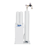
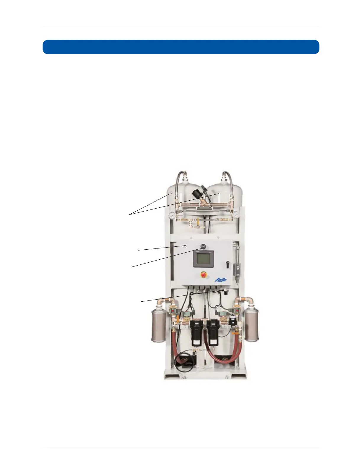
4.1 EXTERNAL COMPONENTS
Figure 4.1 below illustrates the external components viewed from the front of the
oxygen generator.
Adsorbers
Control Panel
Alarm Horn
Oxygen Sample
Regulator
(Set at 1 psig)
AS-G Series Model
Figure 4.1: External Components — Front View
 Loading...