AS-D+—AS-P Series Instruction Manual 35
AirSep Corporation
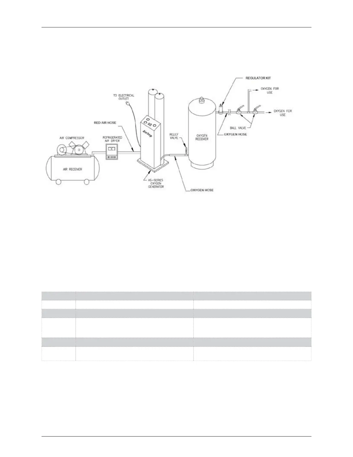
5.3 INSTALLATION INSTRUCTIONS
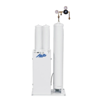
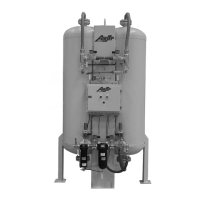
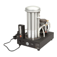
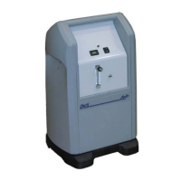
Refer to Figure 5.1 below for the recommended installation arrangement for the
oxygen generator.
Figure 5.1: Typical Installation Arrangement
1. Ensure the oxygen generator is secured to the floor to prevent tipping.
Any additional component such as tanks or compressors should be
secured as well.
2. Connect the red air hose provided with the oxygen generator
accessories, if ordered, from the on-site air supply to the feed air inlet
connection on the oxygen generator. Refer to Table 5.1 to determine
the proper size for the feed air inlet connection and feed air hose for
your model.
Model Feed Air Inlet Connection Size Feed Air Hose Size
AS-D+
⅜” NPT Female tting ⅜” ID minimum
AS-E
½” NPT Female tting ½” ID minimum
AS-G,
AS-J,
AS-K
¾” NPT Female tting ¾” ID minimum
AS-L
1” NPT Female tting 1” ID minimum
AS-N,
AS-P
1½” NPT Female tting 1½” ID minimum
Table 5.1: Feed Air Connection Sizes and Hose Sizes
 Loading...