36 AS-D+—AS-P Series Instruction Manual
AirSep Corporation
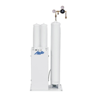
3. Install your oxygen receiver. If AirSep Corporation provided your
oxygen receiver; assemble the receiver as follows (if not assembled):
a. Connect the relief valve assembly to the oxygen inlet port on the
oxygen receiver. Tighten the connection fully.
b. Connect the regulator kit at the oxygen outlet port on the oxygen
receiver. Refer to Figure A.2 for the location of regulator kit installation.
Tighten the connection fully.
Use Teon™ tape to seal the threaded connections on the oxygen
receiver. If AirSep Corporation provided your oxygen receiver,
the threaded connections in the accessory kit were shipped with
Teon™ tape wrapping already applied.
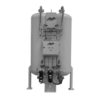
If AirSep Corporation did not provide your oxygen receiver, make sure your oxygen
receiver is sized properly to meet the requirements of your oxygen generator
model. In addition, AirSep Corporation recommends that the oxygen inlet on the
oxygen receiver contain a relief valve and that the oxygen outlet on the oxygen
receiver contain a pressure regulator and pressure gauge or a manual ball valve
and pressure gauge.
3. Connect the oxygen clean hose provided with the oxygen generator
accessories from the oxygen outlet connection on the oxygen
generator to the relief valve assembly at the oxygen inlet port on the
oxygen receiver. Refer to the following table to determine the proper
size for the oxygen outlet connection. If AirSep Corporation did not
provide the hose then ensure that the hose used is properly sized and
is compatible for use with oxygen.
Model Oxygen Outlet Connection Size
AS-D+
¼” NPT Female tting
AS-E,
AS-G,
AS-J
⅜” NPT Female tting
AS-K,
AS-L
¾” NPT Female tting
AS-N,
AS-P
¾” NPT Female tting
Table 5.2: Oxygen Outlet Connection Sizes
 Loading...