14 |Installation OmniAccess 4504, 4604, and 4704 WLAN Switch | Installation Guide
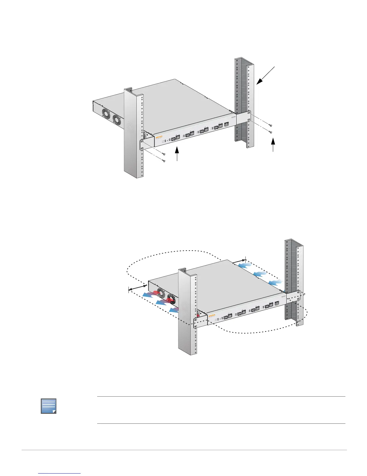
4. Mount the switch within your organization’s rack system using four 12-24 x 5/8” phillips flat head
screws and a suitable screwdriver (see Figure 2).
Figure 2 Rack Mount Installation
5. Leave a minimum of four inches (10 cm) of space on the left and right side of the unit for proper air
flow and ventilation (see Figure 3).
6. Leave additional space in the front and back of the unit to access power cords, network cables, and
LED status indicators (see Figure 3).
Figure 3 Air Flow Requirements
7. Connect the AC power cord (country-specific) to the rear of the unit.
8. Plug the opposite end of the power cord into an electrical outlet to power on the switch.
Standard 19-inch
Rack System
12-24 x 5/8”
Phillips Flat Head Screws
(4x, 2x per bracket)
Switch with Rack Mount
Brackets
Keep Clear for
Air Exhaust
Keep Clear for
Air Intake
Keep Open for
Easy Access
Keep Open for
Easy Access
4 inches (10 cm)
Minimum
OmniAccess 4504, 4604, and 4704 switches do not have a switch for turning power to the unit on or
off. Power to the unit is controlled by connecting or disconnecting the plug on the power cord to or
from an electrical outlet.
 Loading...