Do you have a question about the Alcatel-Lucent OmniSwitch 6250 and is the answer not in the manual?
Lists the OmniSwitch 6250 models covered in this guide.
Lists products not covered by this guide.
Identifies the target audience for this hardware user guide.
Outlines the hardware-related information covered in the guide.
Explains the structure and flow of information within the user guide.
Outlines the sequence of manuals for configuring OmniSwitch 6250.
Lists and describes other user manuals for OmniSwitch 6250 and related products.
Provides information on accessing user guides for OmniSwitch and other products.
Details how to obtain technical support for Alcatel-Lucent products.
Describes the available OmniSwitch 6250 chassis models and their port densities.
Provides a general overview of OmniSwitch 6250 features, including security and applications.
Details hardware and software safeguards for high availability and uninterrupted operations.
Explains automatic and user-driven methods for monitoring switch hardware status.
Covers the initial steps for installing the OmniSwitch 6250 hardware.
Details environmental and electrical requirements for installing the switch.
Provides instructions for unpacking and physically installing the switch chassis.
Guides on connecting network and management cables to the switch.
Explains the process of powering on and booting the OmniSwitch 6250.
Details the initial steps for logging into the switch via the console port.
Explains how to enable access to remote session types like Telnet and SNMP.
Provides instructions for changing the default administrator password.
Guides on configuring the switch's time zone and daylight savings settings.
Covers configuring administrative contact, system name, and location.
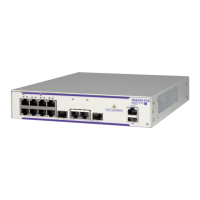
Details the components and specifications of the OS6250-8M model.
Illustrates and describes the components on the front panel of the OS6250-8M.
Illustrates and describes the components on the rear panel of the OS6250-8M.
Lists the technical specifications for the OS6250-8M switch.
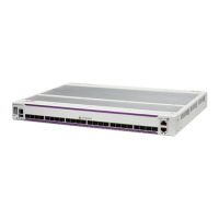
Details the components and specifications of the OS6250-24M/24MD models.
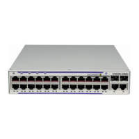
Illustrates and describes the front panel components of the OS6250-24M/24MD.
Illustrates and describes the rear panel components of the OS6250-24M/24MD.
Lists the technical specifications for the OS6250-24M/24MD switches.
Details the components and specifications of the OS6250-24 model.
Illustrates and describes the front panel components of the OS6250-24.
Illustrates and describes the rear panel components of the OS6250-24.
Lists the technical specifications for the OS6250-24 switch.
Details the components and specifications of the OS6250-P24 model.
Illustrates and describes the front panel components of the OS6250-P24.
Illustrates and describes the rear panel components of the OS6250-P24.
Lists the technical specifications for the OS6250-P24 switch.
Explains the meaning of various LEDs on the OmniSwitch 6250 front panel.
Lists the different types of power supplies available for the OS6250 series.
Provides specifications for the internal 30W AC system power supply.
Provides specifications for the internal DC system power supply.
Details specifications for the PS-42W-AC power brick.
Details specifications for the PS-30W-DC power brick.
Details specifications for the 225W AC PoE power supply module.
Describes the OS6250 power supply tray and its specifications.
Provides specifications for the AC power cords included with the product.
Details specific considerations for DC power supply connections and wiring.
Lists the types and lengths of stacking cables used for virtual chassis configurations.
Describes the console port and its default serial connection settings.
Provides pinout details for RJ-45 console, Ethernet, and SFP ports.
Explains the switch behavior when operating temperatures are exceeded.
Describes the switch's behavior during a power loss event and related notifications.
Shows the individual chassis and power supply tray components.
Lists the different mounting kits available for OS6250 switches.
Provides general guidelines for installing the switches.
Offers recommendations for ensuring proper airflow and cooling for the switches.
Specifies the minimum clearance requirements for chassis cooling and access.
Explains different power supply configurations and requirements.
Provides guidelines and steps for assembling OS6250 switches with mounting hardware.
Details how to attach the power supply tray to the side of a chassis for rack mounting.
Specific instructions for installing the OS6250-RM-19 tray for side mounting.
Instructions for mounting two OS6250 chassis side-by-side using the DUAL-MNT kit.
Steps for attaching the power supply tray to the rear of the chassis.
Guides on how to secure power supply bricks and modules into the tray.
Steps for installing power supply bricks into the tray.
Steps for installing power supply modules into the tray.
Detailed instructions and guidelines for rack-mounting the switches.
Important considerations before performing rack-mounting installation.
Step-by-step guide for physically mounting the switch assembly into a rack.
Instructions for mounting the switches on a table or as a freestanding unit.
Guidelines for choosing a location and preparing for table mounting.
Step-by-step instructions for table-mounting the chassis.
Information on wall-mounting the OS6250-8M model.
Guidelines for selecting a location and preparing for wall mounting.
Specific steps for wall-mounting using the OS6250-WALL-MNT kit.
How to connect the switch chassis to AC and DC power sources.
Details on connecting the switch to an AC power outlet.
Steps to power on the switch chassis after connecting power.
Specific connection instructions for the internal DC power supply.
Specific connection instructions for the backup DC power brick.
Guides on how to secure the redundant DC power connector bracket.
Instructions for connecting DC power source wire leads to the switch.
Procedures for hot-swapping power supplies on supported models.
Explains the process of booting the OmniSwitch 6250 switch.
Describes the console port for initial access and management.
Lists the default serial connection parameters for the console port.
Guides on how to change serial connection settings like baud rate and parity.
Shows how to check the status of installed power supplies using CLI commands.
Explains how to monitor chassis hardware status using CLI commands.
How to use `show chassis` command to check overall status.
How to use `show temperature` command to check chassis temperature.
How to use `show fan` command to check fan status.
Lists other useful CLI commands for monitoring chassis hardware.
Explains how to use front panel LEDs for visual monitoring of the chassis.
Directs users to another guide for SFP/XFP transceiver installation.
Outlines the topics covered in the chapter regarding PoE management.
Lists general specifications for Alcatel-Lucent's PoE support.
Shows how to check the status of installed PoE power supplies.
Details how to configure PoE settings and parameters on the switch.
Lists the default configuration values for PoE parameters.
Guides on enabling and disabling PoE functionality on ports and slots.
How to adjust the maximum milliwatts available to an individual port.
How to adjust the maximum watts available to the entire switch for PoE.
How to assign priority levels (low, high, critical) to ports for power management.
Explains how priority disconnect manages power budget deficits.
How to enable or disable the priority disconnect feature.
How to monitor PoE statistics and settings using CLI commands.
Outlines the topics covered in the chapter on managing OmniSwitch 6250 stacks.
Lists the technical specifications related to OmniSwitch 6250 stacking.
Instructions on changing the stacking mode for Metro models.
Provides an overview of OmniSwitch 6250 switches configured in a stack.
Describes the different roles assigned to switches within a stack.
Details the primary and secondary roles for stack management modules.
Explains the methods used to select the primary management module in a stack.
How the lowest MAC address is used to determine the primary switch in a stack.
How saved slot numbers influence primary management module selection.
How switch uptime can override MAC address or saved slot for primary selection.
Explains methods for selecting the secondary management module.
How connection to the primary switch determines the secondary role.
How saved slot info determines the secondary management module.
Describes the default role of idle modules in a stack.
Explains the pass-through mode and conditions that trigger it.
Steps to resolve pass-through mode caused by duplicate slot numbers.
Details how switches in a stack are connected using stacking cables.
Explains the importance and setup of redundant stacking cable connections.
How to check the status of redundant stacking cable connections.
Explains the assignment of unique slot numbers to modules in a stack.
How the system assigns slot numbers when no configuration is present.
How users can manually assign slot numbers to stack modules.
Steps to clear manual slot assignments and revert to dynamic numbering.
Procedures for adding or removing modules from a stack without disruption.
Guidelines for safely removing switches from a stack.
Guidelines for safely adding switches to a stack.
Instructions and considerations for merging multiple stacks.
General information on soft-booting switches within a stack.
Steps to reload the primary management module and its impact.
Steps to reload the secondary management module and its impact.
How to reload modules operating in idle status within a stack.
How to reload modules that are in pass-through mode.
Procedure for performing a full reboot of the entire virtual chassis.
Explains how software is synchronized during a full stack reload.
How saved slot numbers affect reload outcomes.
Guidelines to prevent stack splitting during reload operations.
Warning against reloading non-adjacent switches at the same time.
Importance of maintaining redundant stacking cable connections.
How to manually force the secondary module to take over the primary role.
Process of copying files between management modules for synchronization.
How synchronization occurs automatically during a full stack reload.
Explains the SSP feature for detecting and handling stack splits.
Defines key terms and components related to Stack Split Detection.
Describes the fundamental operation of stack split detection.
Explains the different protection states within SSP.
Methods for recovering a stack from a split state.
Steps for manually recovering a stack split.
How automatic recovery works after a stack split.
Lists CLI commands useful for monitoring stack conditions.
Lists specific CLI commands for stack monitoring.
How to monitor stack operations using front panel LEDs.
Statement of compliance with relevant European directives.
Table indicating hazardous substances in product components for China.
Warning about chemicals known to cause cancer and birth defects in California.
Statement regarding the proper disposal of electronic equipment.
Lists safety agency certifications and EMI/EMC standards met by the product.
Lists various safety certifications obtained by the product.
Lists electromagnetic interference and compatibility standards complied with.
Compliance statement regarding FCC Class A digital device regulations.
Statement of compliance with Canadian radio noise emission limits.
Statement of compliance with Japan Approvals Institute of Telecommunications Equipment.
Warning about potential radio interference in domestic environments.
Statement related to electromagnetic emission standards in Korea.
Statement regarding Voluntary Control Council for Interference by Information Technology Equipment.
Warning about potential radio interference in residential environments in Taiwan/China.
Warning against installing network cables outdoors and following manufacturer requirements.
Collection of safety warnings translated into multiple languages.
Safety precautions for lifting the switch chassis, requiring two people.
Warning to avoid connecting/disconnecting cables during an electrical storm.
States that only qualified personnel should install or maintain the equipment.
Warning regarding invisible laser radiation from fiber-optic ports.
Warning to disconnect all power before servicing or moving the unit.
Emphasizes the need for proper wiring and earthing connections.
Advises users to read the guide for important safety information before use.
Recommends installing the equipment in a secure location with limited access.
Warning about electrostatic discharge (ESD) and the need for grounding.
| Model | OmniSwitch 6250 |
|---|---|
| Port Configuration | Fixed |
| Uplink Ports | 4 x 10G SFP+ |
| Operating System | AOS (Alcatel-Lucent Operating System) |
| Jumbo Frame Support | Yes |
| Product Type | Switch |
| Ports | 48 |
| Power over Ethernet (PoE) | Yes |
| Form Factor | Rack-mountable |
| Management | CLI, Web, SNMP |
| MAC Address Table Size | 16, 000 |
| Routing Protocol | OSPF, RIP, BGP |
| Power | AC |
| Power Supply | Dual redundant |
| Operating Temperature | 0°C to 45°C |
| Operating Humidity | 10% to 90% (non-condensing) |