Do you have a question about the Alcatel-Lucent OmniSwitch 6900 and is the answer not in the manual?
Information in this guide applies only to OmniSwitch 6900 switches.
Audience is network administrators and IT support personnel.
Read when ready to familiarize with switch hardware components.
Describes hardware-related information like features, specs, airflow, hot-swapping, CLI commands.
Focuses on hardware, not software configuration. Recommends other guides for software.
Each chapter focuses on a specific hardware component or set of components.
Guide to get switch up and running: unpacking, mounting, basic setup.
Covers hardware specs, component procedures, basic software features.
Covers network configuration, VLANs, routing protocols, etc.
Comprehensive information on all CLI commands supported by the switch.
Technical specs and procedures for chassis, power supplies, fans, and modules.
Complete CLI command reference: syntax, examples, MIB mappings.
Procedures for switch integration, architecture, access, files, SNMP, WebView.
Network config, Layer 2/3 features, protocols, security, QoS, link aggregation.
Advanced routing: OSPF, BGP, multicast protocols.
Data center switching: SPBM, DCB, vNP, EVB protocols.
SFP and XFP transceiver specs and compatibility.
Information from Alcatel-Lucent Customer Support.
Critical problem reports, feature exceptions, and limitations.
Details 7x24 support, software updates, hardware replacement, and contact info.
Introduction to OmniSwitch 6900 series, highlighting key features like redundancy and ports.
Information on power supply redundancy, refer to Chapter 3.
Action of adding/removing components without powering off the switch.
Monitors switch operations via sensors and LEDs.
Monitors operations via built-in sensors, sends traps for errors like over-threshold temperature.
Provide visual status information on front and rear panels for hardware and software status.
Accesses status via CLI commands, using 'show' commands for output.
Procedures for installing the switch hardware, including items required and site preparation.
Lists tools and accessories needed for installation.
Covers environmental and electrical requirements for installation.
Specifies temperature, humidity, and airflow clearances.
Details power connection requirements and safety considerations.
Covers redundant power and surge protection guidelines.
Recommendation for using separate circuits for redundant AC power supplies.
Recommendations and guidelines to protect equipment against electrical surges.
Details items included and weight considerations for the switch.
Lists the items that come with the OmniSwitch 6900.
Details the weight of the chassis when empty and fully populated.
Ensures proper airflow by placement and maintaining minimum clearances around the switch.
Covers switch mounting, cabling, and port connection guidelines.
Information on mounting OmniSwitch 6900 switches.
Connects network and management cables for network applications.
Warning against installing exposed network cables outdoors.
Provides serial connection for initial login and configuration.
Details default baud rate, parity, data bits, and cable settings.
Specifies cable type requirements for EMP connection.
Instructions for powering on the switch after installation and connection.
Describes LED behavior during the boot process.
Steps for initial login, IP setup, password change, and basic configuration.
Details how to log in using default credentials and the welcome banner.
Configures the IP address and subnet mask for the Ethernet Management Port.
Covers unlocking session types and changing login passwords.
Enables remote session types like Telnet, FTP, and SNMP.
Steps to change the default 'admin' user password for security.
Sets system time, date, and optional parameters.
Configures the switch's time zone and daylight saving time settings.
Sets the current date and time on the switch.
Configures administrative contact, system name, and location.
Sets a contact person or department for switch inquiries.
Defines a user-friendly text description for the switch.
Assigns a physical location identifier for the switch.
Reviews and saves system configuration changes.
Displays current configuration changes made to the switch.
Saves the configured basic switch information using the 'write memory' command.
Details specifications for various chassis models.
Information on mounting the switch in racks or standalone.
Covers power supply units, their types, and redundancy features.
Information on monitoring and managing switch temperatures.
Details the fan tray, its function, and airflow direction.
Instructions for monitoring chassis status using CLI commands.
Diagram and description of the front panel components of the OS6900-X20 chassis.
Diagram and description of the rear panel components of the OS6900-X20 chassis.
Diagram and description of the front panel components of the OS6900-X40 chassis.
Diagram and description of the rear panel components of the OS6900-X40 chassis.
Detailed specifications for OS6900-X20 and OS6900-X40 chassis models.
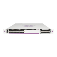
Diagram and description of the front panel components of the OS6900-X72 chassis.
Diagram and description of the rear panel components of the OS6900-X72 chassis.
Detailed specifications for the OS6900-X72 chassis model.
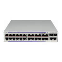
Diagram and description of the front panel components of the OS6900-T20 chassis.
Diagram and description of the rear panel components of the OS6900-T20 chassis.
Diagram and description of the front panel components of the OS6900-T40 chassis.
Diagram and description of the rear panel components of the OS6900-T40 chassis.
Detailed specifications for OS6900-T20 and OS6900-T40 chassis models.
Diagram and description of the front panel components of the OS6900-Q32 chassis.
Diagram and description of the rear panel components of the OS6900-Q32 chassis.
Detailed specifications for the OS6900-Q32 chassis model.
Diagrams and descriptions of the OS6900-V72 chassis front and rear panels.
Diagram and description of the front panel components of the OS6900-V72 chassis.
Diagram and description of the rear panel components of the OS6900-V72 chassis.
Detailed specifications for the OS6900-V72 chassis model.
Diagrams and descriptions of the OS6900-C32 chassis front and rear panels.
Diagram and description of the front panel components of the OS6900-C32 chassis.
Diagram and description of the rear panel components of the OS6900-C32 chassis.
Detailed specifications for the OS6900-C32 chassis model.
Diagrams and descriptions of the OS6900-T48C6 chassis front and rear panels.
Diagram and description of the front panel components of the OS6900-T48C6 chassis.
Diagram and description of the rear panel components of the OS6900-T48C6 chassis.
Detailed specifications for the OS6900-T48C6 chassis model.
Diagrams and descriptions of the OS6900-X48C6 chassis front and rear panels.
Diagram and description of the front panel components of the OS6900-X48C6 chassis.
Diagram and description of the rear panel components of the OS6900-X48C6 chassis.
Detailed specifications for the OS6900-X48C6 chassis model.
Specifies maximum connector dimensions for RJ45 cables for clearance.
Explains the meaning of various status LEDs on the chassis.
Details status LED states for V72, C32, T48C6, X48C6 models.
Describes port LED behavior for Q32 and X72 models, differing from others.
Explains LED indicators for 4x10G splitter cables.
Details the OS-XNI-U4 expansion module, including ports and power consumption.
Details the OS-XNI-U12 expansion module, including ports and power consumption.
Details the OS-QNI-U3 expansion module, including ports and power consumption.
Details the OS-HNI-U6 expansion module, including ports and power consumption.
Details the OS-XNI-T8 expansion module, including ports, cable support, and distances.
Details the OS-XNI-U12E module supporting 10G SFP+ or Fibre Channel.
Describes the status LED behavior for plug-in modules.
Covers ambient temperature, airflow, loading, circuits, and earthing.
Ensures proper airflow by placement and maintaining minimum clearances around the switch.
Explains front-to-rear and rear-to-front airflow paths.
Describes how air flows from front to rear through the chassis.
Describes how air flows from rear to front through the chassis.
Covers consequences of airflow mismatch and component color coding.
Explains consequences of mismatched fan tray/PSU airflow direction.
Identifies color coding for rear-to-front components to avoid mismatch.
Role of blank panels in airflow regulation and component protection.
Guidelines and steps for installing the chassis into a standard 19-inch rack.
Steps to install the chassis using mid-mount flanges for support.
Instructions for placing the chassis on a stable surface as a standalone unit.
Details chassis weight for standalone placement.
Ensures airflow and AC outlet access for standalone units.
Guidelines and supported scenarios for hot-swapping plug-in modules.
Notes for OS6900-X40 switches regarding module addition.
Step-by-step procedure for hot-swapping plug-in modules.
Step-by-step instructions for inserting plug-in modules into the chassis.
Step-by-step instructions for removing plug-in modules from the chassis.
Details the AC power supply for specific OmniSwitch models.
Diagram and specifications of the AC power supply front panel.
Explains the meaning of the LED states for AC power supplies.
Details the AC power supply for OS6900-V72 and OS6900-C32 models.
Diagram and specifications of the AC power supply front panel.
Explains the meaning of the LED states for AC power supplies.
Details the AC power supply for OS6900-T48C6 and OS6900-X48C6 models.
Diagram and specifications of the AC power supply front panel.
Explains the meaning of the LED states for AC power supplies.
Details the DC power supply for specific OmniSwitch models.
Diagram and specifications of the DC power supply front panel.
Explains the meaning of the LED states for DC power supplies.
Details the DC power supply for OS6900-V72 and OS6900-C32 models.
Diagram and specifications of the DC power supply front panel.
Explains the meaning of the LED states for DC power supplies.
Details the DC power supply for OS6900-T48C6 and OS6900-X48C6 models.
Diagram and specifications of the DC power supply front panel.
Explains the meaning of the LED states for DC power supplies.
Procedures for connecting DC cable harnesses to the chassis and power source.
Instructions for connecting the DC cable to the power supply connector.
Guidelines for connecting the DC cable to the power source.
Important guidelines for connecting DC power supplies and cables.
Details grounding requirements and methods for the chassis.
Explains DC cable wire connections and polarity.
Step-by-step instructions for installing power supplies into the chassis.
Step-by-step instructions for removing power supplies from the chassis.
Details fan tray airflow models and matching requirements with power supplies.
Step-by-step instructions for removing and replacing the chassis fan tray.
Instructions for grounding the chassis using the rear grounding lug.
How to view basic and detailed slot information via CLI commands.
Importance of operating temperature and how to check it.
Details warning and danger thresholds and error severity levels for temperature.
Actions to take when the warning temperature threshold is exceeded.
Consequences of exceeding the danger threshold and how to address it.
How to monitor fan operation and check fan tray status via CLI commands.
Pinout details for the RJ45 console port.
Pinout details for USB console ports.
Details pinouts for 10/100 and Gigabit Ethernet ports.
Pinout details for 10/100 Ethernet ports.
Pinout details for Gigabit Ethernet ports.
States compliance with essential requirements and other EU directives.
Product end-of-life disposal information for EU member states.
Table indicating hazardous substances in product components as per China RoHS.
Table indicating hazardous substances in product components as per Taiwan RoHS.
Warning about exposure to chemicals known to cause cancer or reproductive harm.
Lists safety and EMC standards that the product complies with.
List of various international safety standards met by the product.
List of various international EMC standards met by the product.
Compliance with FCC limits for Class A digital devices to prevent radio interference.
Statement regarding Class A limits for digital apparatus radio noise emissions in Canada.
Statement regarding compliance with Japan Approvals Institute of Telecommunications Equipment (JATE).
Includes warnings for CISPR22, Korea, VCCI, Taiwan, and Laser safety.
Warning about potential radio interference in domestic environments for Class A products.
Statement regarding business equipment registration for electromagnetic conformity in Korea.
Compliance with Voluntary Control Council for Interference by Information Technology Equipment standards.
Warning about potential radio interference in residential environments for Class A products.
Warning about Class 1M laser radiation when apertures are open.
Includes warnings for network cables, blank panels, storms, and installation.
Warning against installing exposed network cables outdoors.
Importance of keeping blank panels installed for airflow and protection.
Avoid connecting/disconnecting cables during an electrical storm.
Only knowledgeable personnel should install or maintain the equipment.
Warnings for laser radiation, operating voltage, and power disconnection.
Warning about invisible laser radiation from open apertures and protective covers.
Keep hands away from power supply bays and backplane to avoid electrical shock.
Disconnect all power connections before servicing or moving the unit.
Covers earthing requirements and DC power connection warnings.
Ensures proper connection to a wired and earth receptacle for safety.
Requirement for connecting DC power supply ground wire to Common Earth Ground for EMC/EMI.
Includes warnings on reading safety info, restricted access, and ESD protection.
Emphasizes reading 'Getting Started' for important hardware safety information.
Equipment must be installed in a secure location limiting access to authorized personnel.
Procedures to eliminate ESD before handling components.
| Brand | Alcatel-Lucent |
|---|---|
| Model | OmniSwitch 6900 |
| Category | Switch |
| Language | English |