MicrowaveradiorelaylinkZENITH80
12/52 1.2
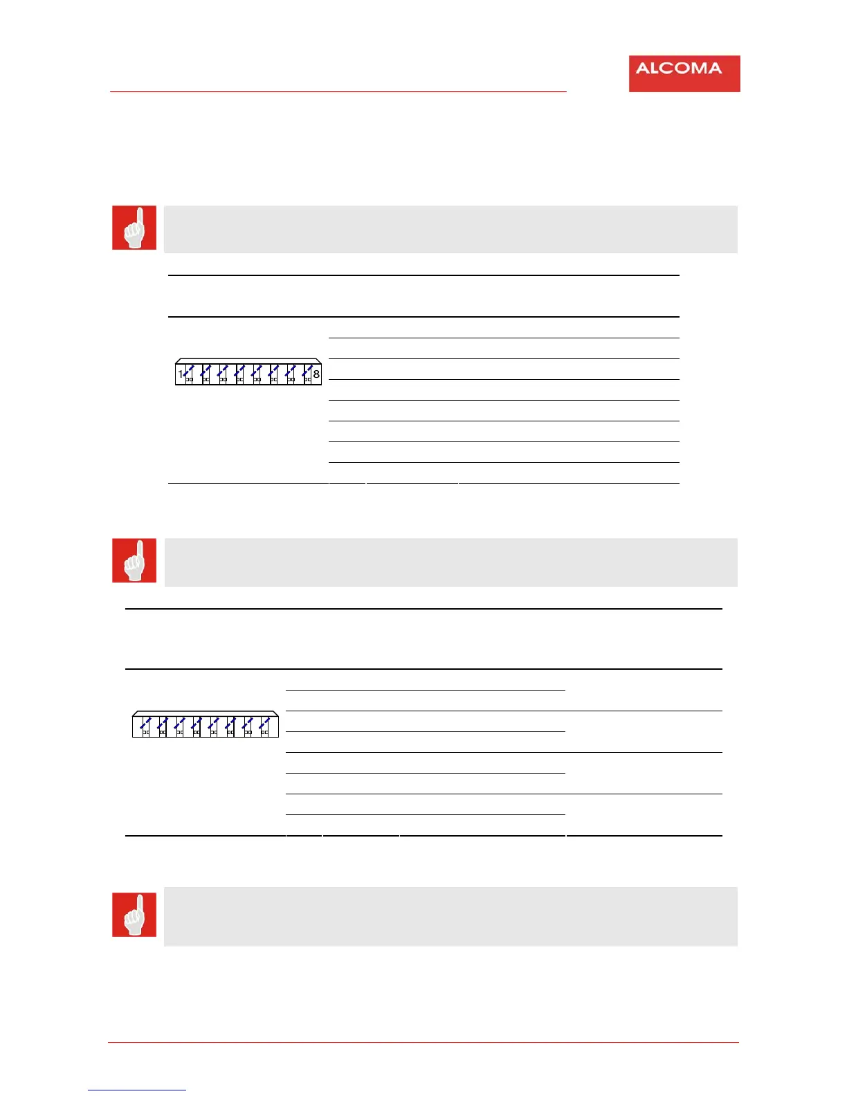
2.2.2 OutputConnectors
Cuttingbox"Krone"fortheline2
Line2doesnotcontainpowerfeeding.
(ConnectoriswiredasamirrorofODUconnector).
Themarkingofcableconductors
Wiring Pins Description
S‐STPCat7
1 A+ White
2 A‐ Green
3 B+ White
4 B‐ Orange
5 C+ Blue
6 C‐ White
7 D+ White
8 D‐ Brown
Table2 Theprotectedterminal box‐cuttingbox“KRONE“fortheline2
Cuttingbox"Krone"fortheline3+Power
Line2containspowerfeeding.
(ConnectoriswiredasamirrorofODUconnector).
Themarkingofcable
conductors
Powerfeeding
Wiring Pins Description
S‐STPCat7
1 A+ White
2 A‐ Green
‐
3 B+ White
4 B‐ Orange
+
5 C+ Blue
6 C‐ White
‐
7 D+ White
1
8
8 D‐ Brown
+
Table3 Theprotectedterminal box‐cuttingbox“KRONE“fortheline3+power
ThecableACOMES‐STPCat7hasitsshieldingconnectedtogroundthroughthemetalinput
grommet.Ifthecablehastheshieldingcomingoutthroughoneconductoritcanbeconnected
toanyshieldingpin.