User Instructions
General Assembly
Connecting the Lower shaft
to the Upper shaft
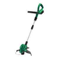
Prior to use, it is necessary to connect the lower
shaft (15) to the upper shaft (11), and to assemble
the guard (16), and the spool and line assembly (21).
NOTE: Before assembling the shafts, ensure the
protective plastic sleeve is removed from the shaft
of the line trimmer.
1. Remove the shaft locking knob (14) from the
accessory bag. (Fig A)
2. Insert the lower shaft (15) into the upper shaft
(11), and rotate until the locating pin clicks into
position. You will hear a click. (Fig B)
3. Insert the shaft locking knob (14) into the shaft
connector (13) and tighten firmly in a clockwise
direction. (Fig C)
Assembling the Guard
1. Remove the bolt from the guard (16). (Ensure
you leave the hex nut as it is on the opposite
side of the guard).
2. Place the guard (16) on the opposite side of the
clamp, and push it over the lower shaft (15) into
position on the clamp. (Fig D). Ensure you line
up the holes on the clamp with the holes in the
guard (16).
NOTE: Ensure that the guard is the correct way
up i.e when in the correct position the cut off
knife (19) is exposed to the lower end of the line
trimmer, not facing up towards the motor.
A.
B.
C.
D.
General Assembly

 Loading...