PODD – Installation, Operation and Maintenance Manual
A l e n c o n S y s t e m s L L C - P a g e | 20
7.4.3 PODD Connectors
Each PODD has three ports which are labeled on the bottom of the front mounting plate.
To connect a cable to any of these ports:
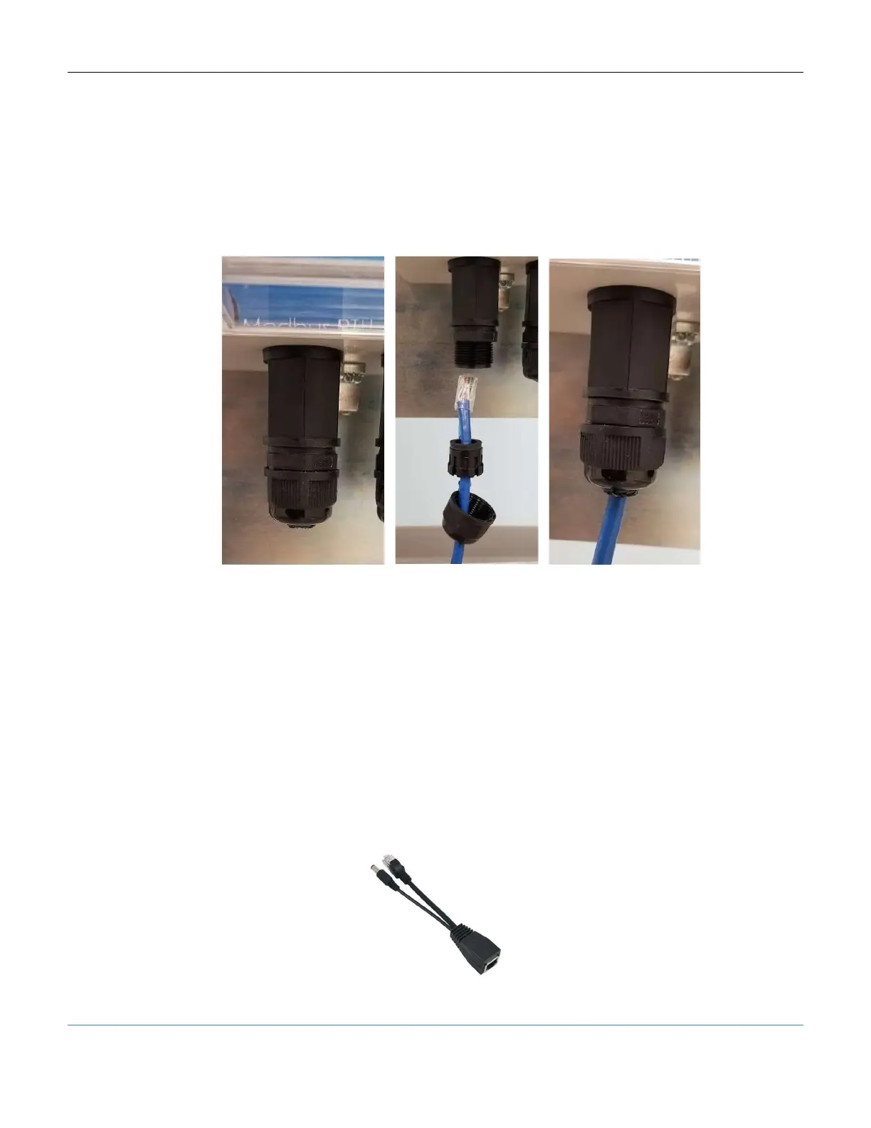
1. Remove the water proof cap and grommet.
2. Feed the cable though the removed cap and grommet.
3. Replace the cap and grommet, tightening to reseal the port.
Figure 15: Water-proof wiring on the PODD
7.5 Powering
7.5.1 Modbus RTU Power
The PODD is most commonly powered via a 24V signal from the networked Alencon
device (SPOT, BOSS, or GARD). Simply connect a Cat5e (or newer) cable between the
peripheral device comms port and the PODD ModbusRTU port. PODD should turn on
within 2 minutes and green LED indicator will turn on when ready.
7.5.2 Network Side PoE Power
When using the PODD in a lab setup where power from Alencon devices is not readily
available, a POE injector is a convenient solution. A POE injector combines a network
connection and power into an RJ45 port as seen below.
Figure 16: POE Injector