10
6
7
8
The indication unit has one or two micro switches or an
inductive proximity switch.
Study the instructions carefully.
The items refer to the drawings and the parts list on the
pages 42-43.
5. Fitting indication equipment, 25-101.6 mm/DN25-100, optional extra
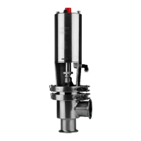
Inductive proximity switch unit:
1. Assemble and fit the switch unit
2. Turn ring (56) so that the edges of holder (51)
guide its movements.
3. Fix the switch unit by means of screws (58).
9
10
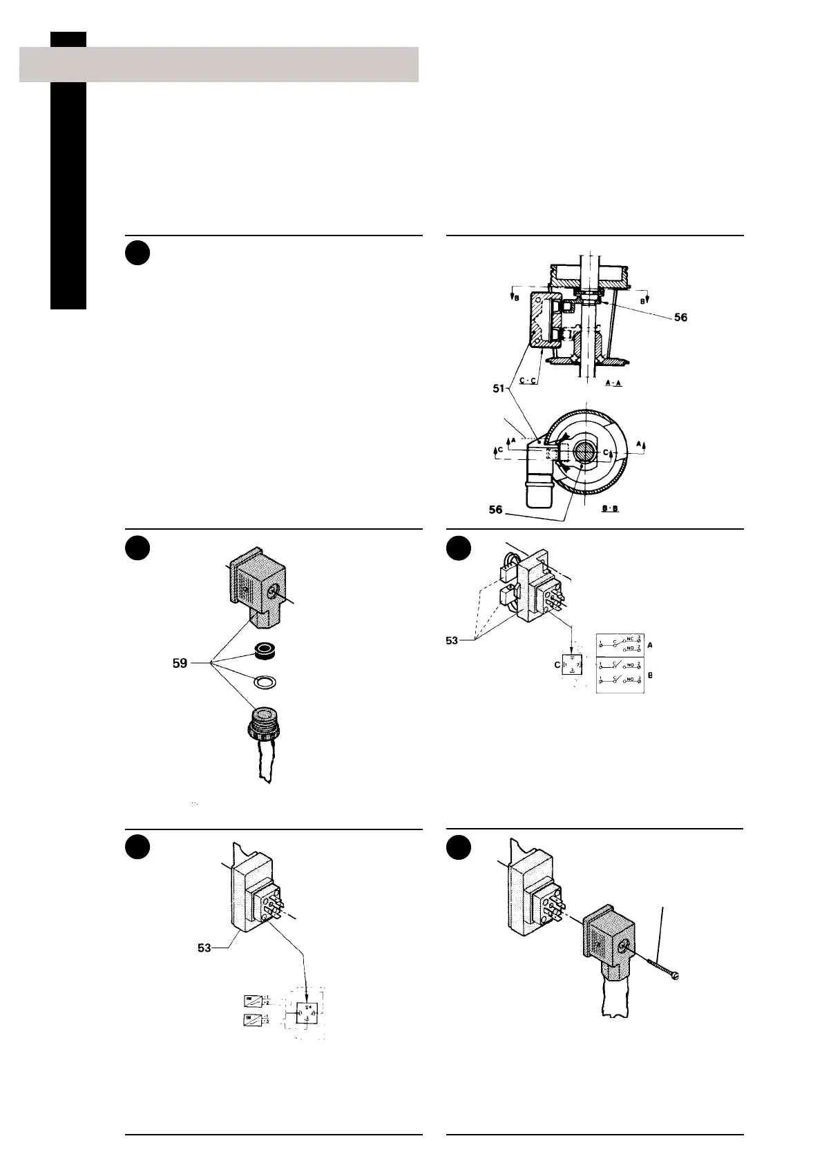
Fit the cable through the cable gland and assemble
cable socket (59).
Micro switch unit:
Connect the cable to switch unit (53) as shown in
the wiring diagram.
Inductive proximity switch unit:
Connect the cable to switch unit (53) as shown in
the wiring diagram.
Tighten screw (59) firmly.
NOTE!
The cable gland should be sealed with silicone
rubber under extreme conditions.
58
Cable
Wiring diagram
Wiring diagram
Male connector
(pin side)
Turn the
cable outlet
downwards!
59
Ø = Connected in cable connector
A = One micro switch
B = Two micro switches
C = Male connector (pin side)
Installation