4
4
2
6
1
5
Installation
The instruction manual is part of the delivery.
Study the instructions carefully.
The items refer to the drawings and the parts list on the
pages 22-37.
The valve is supplied as separate parts as standard (for
welding).
The valve is assembled before delivery, if it is supplied
with fittings.
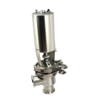
3
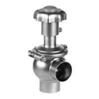
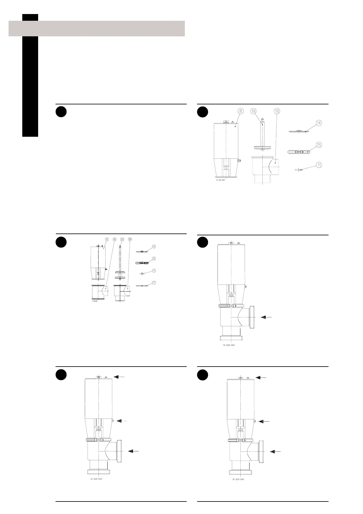
Change-over valve:
1. Complete actuator with bonnet (8).
2. Clip assembly (11).
3. Lip seal (14).
4. Two clamps (15).
5. Valve plug (20).
6. Two valve bodies (16, 18).
7. Valve body seal ring (17).
Remove possible packing materials from the valve/
valve parts.
Inspect the valve/valve parts for visible transport
damages.
Remove
packing
materials!
Avoid damaging the valve/valve parts.
Inspection!
Caution!
1. Unpacking/Delivery
CAUTION!
Alfa Laval cannot be held responsible for incorrect
unpacking.
Check the delivery for:
1. Complete valve, stop valve or change-over
valve (see 2 and 3).
2. Delivery note.
3. Instruction Manual.
Please note that the design of sizes DN125-150
differs from that of sizes 25-101.6 mm/DN25-100.
The differences can be seen on pages 22-29 and
30-37.
The drawings in this manual show sizes 25-101.6
mm/DN25-100
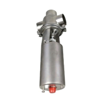
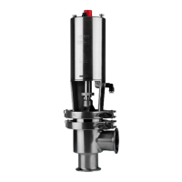
Stop valve:
1. Complete actuator with bonnet (8).
2. Clip assembly (11).
3. Lip seal (14).
4. Clamp (15).
5. Valve plug (19).
6. Valve body (16).