5
1. Place the valve in the trestle.
2. Make sure that the actuator rests on the
rubber linings on the trestle support plates.
3. Dismantle/reassemble the valve.
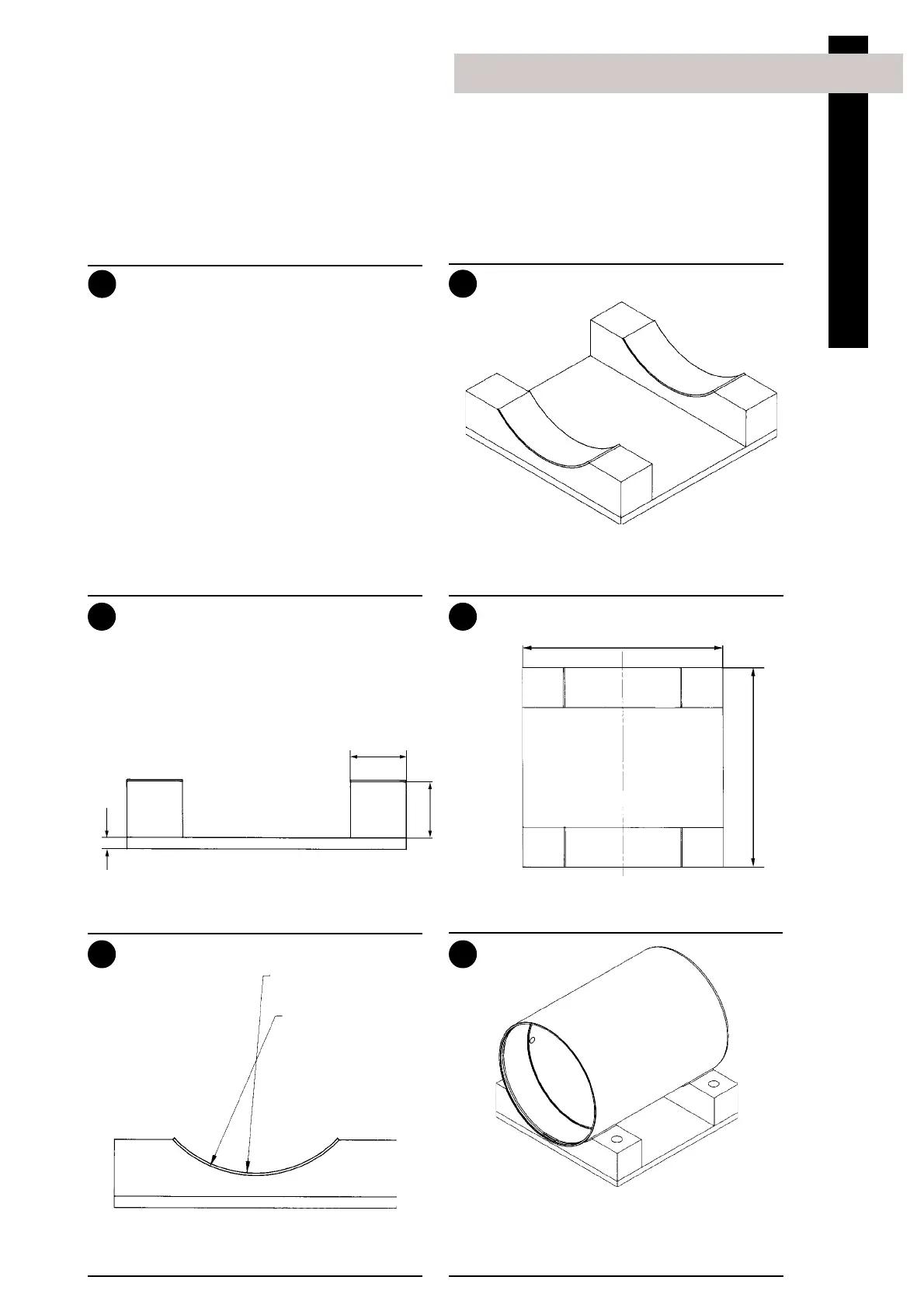
Trestle
50
50
Side view
250
250
Top view
R 99.5
R 101.5
End view
10
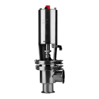
Installation
The valve sizes DN125-150 are very heavy.
Therefore Alfa Laval recommends manufacturing and
usage of auxiliary equipment. A proposal is given below.
2. Recommended auxiliary equipment (DN125/150)
Please note that the auxiliary equipment cannot be
supplied by Alfa Laval.
The item refers to the drawings and parts list on pages
30-37.
1
1
2
43
5 6
6
For lifting the valve:
Screw an eye bolt (6 mm) into top pin (23).
Using a small hook crane or similar, lift the valve
by the eye bolt.
Trestle:
- The purpose of the trestle is to support the valve
during dismantling and reassembly.
- The trestle is made of a base plate, two support
plates, two rubber linings and four bolts.
- The rubber linings are attached to the support
plates so that the valve/actuator will rest on
these.
- To prevent the valve from turning during
dismantling and reassembly the trestle must be
made with the correct measurements (see 3, 4
and 5). All measurements are in mm.