8
1
2
5
6
3
4
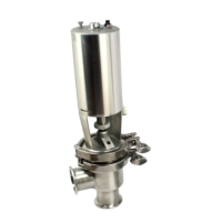
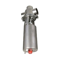
The valve can be fitted with an oil damper if water
hammer occurs when the valve closes in the flow
direction.
The items refer to the drawings and the parts list on
pages 38-41.
Study the instructions carefully and pay special
attention to the warnings!
NC = normally closed.
A/A = air/air activated.
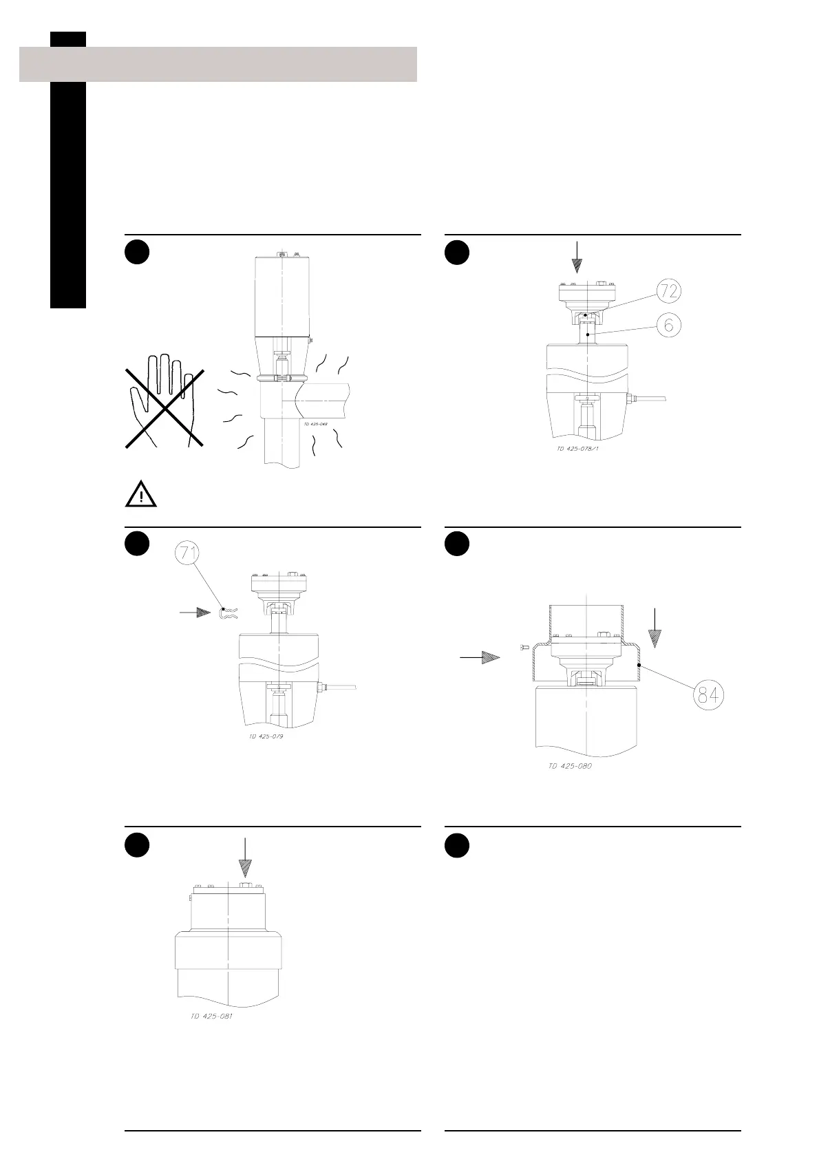
4. Fitting of oil damper, 25-101.6 mm/DN25-100, optional extra
Fill further oil through the plug hole if large air
bubbles occur under the plexiglas cover.
NOTE!
There should be a small air bubble which equalizes
changes in the pressure because of temperature
changes.
Removal/dismantling:
Remove the damper by following the instructions in
reverse order.
Pre-use check:
1. Supply compressed air to the actuator.
2. Open and close the valve several times to
ensure that it operates smoothly.
Pay special attention to the warnings!
Never touch the valve or the pipelines when
processing hot liquids or when sterilizing.
Burning danger!
1. Supply compressed air to the actuator.
Pay special attention to the warnings!
2. Fit the damper so that damper piston rod (72)
enters actuator piston rod (6).
Oil type SAE 40
Ensure that
no other
equipment
is fitted on the
actuator top!
1. Fit protective hood (84).
2. The valve is now ready for operation.
1. Connect the two piston rods by means of clip
(71).
2. Release compressed air to the actuator.
Pay special attention to the warnings!
Air (NC, A/A)
Installation
Air (NC, A/A)