7
Valve size A (mm) B
1
(mm) B
2
(mm)
DN25/25 mm 200 537 647
DN40/38 mm 230 550 730
DN50/51 mm 290 550 730
DN65/63.5 mm 350 550 730
DN80/76 mm 390 600 780
DN100/101.6 mm 490 650 830
DN125 580 730 920
DN150 640 730 920
1
2
4
3
Study the instructions carefully.
The valve is supplied as separate parts to facilitate the
welding.
The items refer to the drawings and the parts list on the
pages 22-37.
Check the valve for smooth operation after welding.
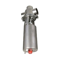
3. Welding
Always weld the valve so that the valve body seal
ring can be replaced (change-over valve).
Maintain the minimum clearances (A and B) so that
the lower valve body and plug (change-over valve)
and the actuator with the internal parts can be
removed.
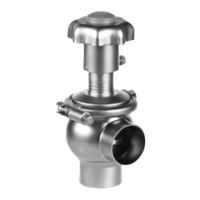
Stop valve:
Assemble the valve in accordance with the
instructions 2-5 on page 18.
Pay special attention to the warnings!
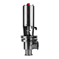
Change-over valve:
Assemble the valve in accordance with the instruc-
tions 2-6 on page 18.
Pay special attention to the warnings!
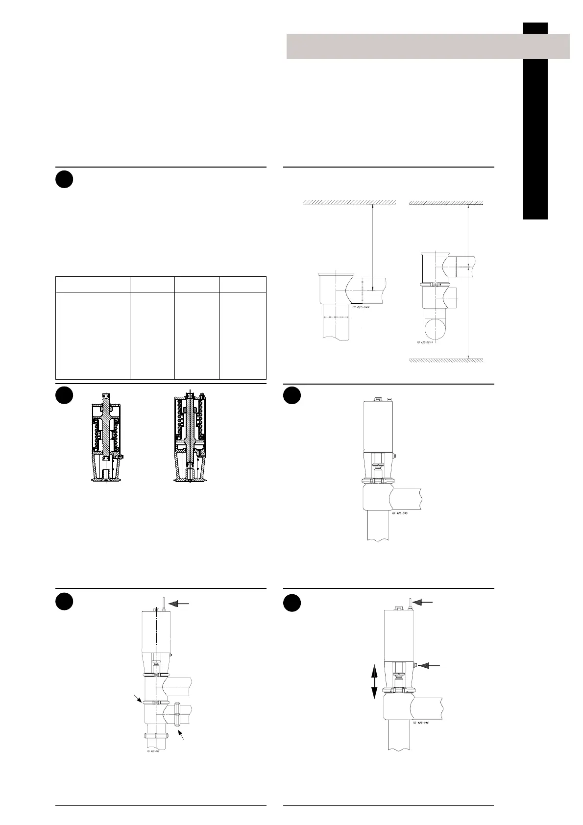
Pre-use check:
1. Supply compressed air to the actuator.
2. Open and close the valve several times to
ensure that it operates smoothly.
Pay special attention to the warnings!
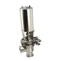
Change-over valve
(upper valve body)
Stop valve
B
1
B
2
(incl. top unit)
Fit seal ring (17)
correctly!
Remember
seal rings!
Air
Open/close!
Installation
B
1
B
2
(incl.
top unit)
A
5
SRC 25 mm stop valve
The 25 mm actuator is only for use on the SRC 25
mm stop valve.
Warning: When changing from NC to NO please
note that the actuator is spring-loaded. For safety,
place a "Spring-loaded" warning label (ordered
from Technical Support at Alfa Laval) on the valve.
Air (NO/AA)
Air (NC/AA)