5Installation
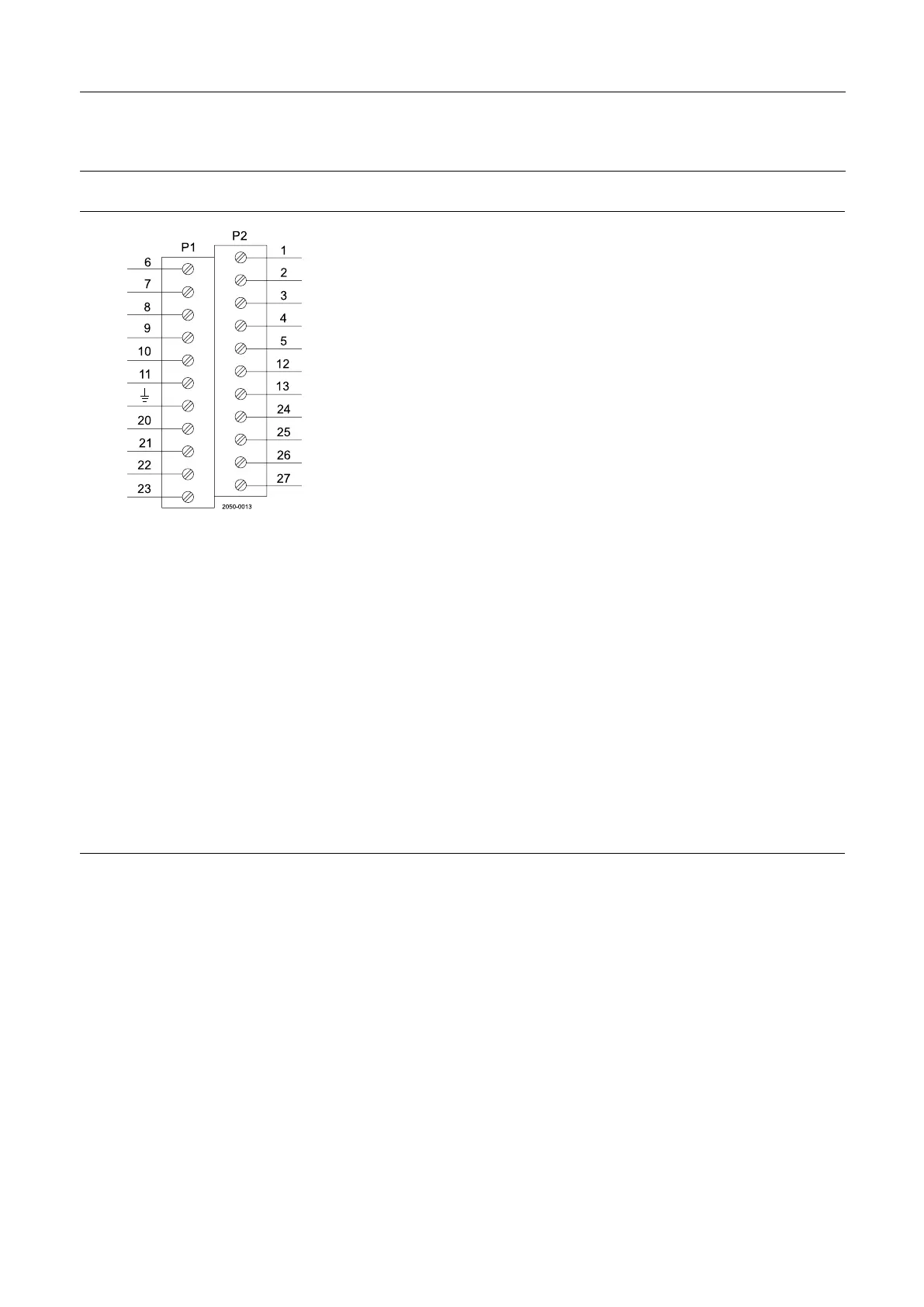
5.6Electricalconnection,internal-AS-Interface
6
ASI+(BN,brown)
1
N/C
7
ASI-(BU,blue)
2
N/C
8
N/C
3
N/C
9
N/C
4
N/C
10
N/C
5
N/C
11
N/C
12
PWMJumper**)
Eart-
h
Earth13
PWMJumper**)
20
Solenoidcommongrey
24
Seat-lift1“upper”*)
21
Solenoid1,grey
25
Seat-lift2“lower”*)
22
Solenoid2,grey
26
Supply+*)
23
Solenoid3,grey
27
Supply-*)
T T
T
able able
able
2. 2.
2.
Note! Note!
Note!
*)Ifusingexternalsensor,thesensormustbeactive/activatedwhenperformingaset-uproutineofthecontrolhead.
Terminals24,25,26and27canbeusedforexternalseatliftsensorsaswellasforanydigitalinput.Alwaysuseanexternal
PNPsensor.Twoexternalsignalscanbeconnected;theseareassociatedwithfeedbacksignal3(seatlift1)and4(seatlift
2).Externalsensormustalwaysbea8-30VDCPNP3wiresensor.Connect(-)commononterminal27and(+)common
onterminal26.Thesignalsfromtheexternalsensorsareassociatedasfollows:sensorsignalonterminal24(seatlift1)
associatedwithfeedback3(seatlift1)andsensorsignalonterminal25(seatlift2)associatedwithfeedback4(seatlift2).
**)
Jumperpresent=PWM.Reducingpowerconsumptionofsolenoidvalves.
***)
Internalconnections:Terminalsforconnectionforthesolenoidsmountedinternallyinthecontrolhead.Thenumberof
solenoidsactuallymountedinthecontrolheadcouldbe0-3.Thesignalsaretakendirectlyfromtheterminalrow.
Note! Note!
Note!
Remembertoisolatewiresthatarenotinuse.
23