5Installation
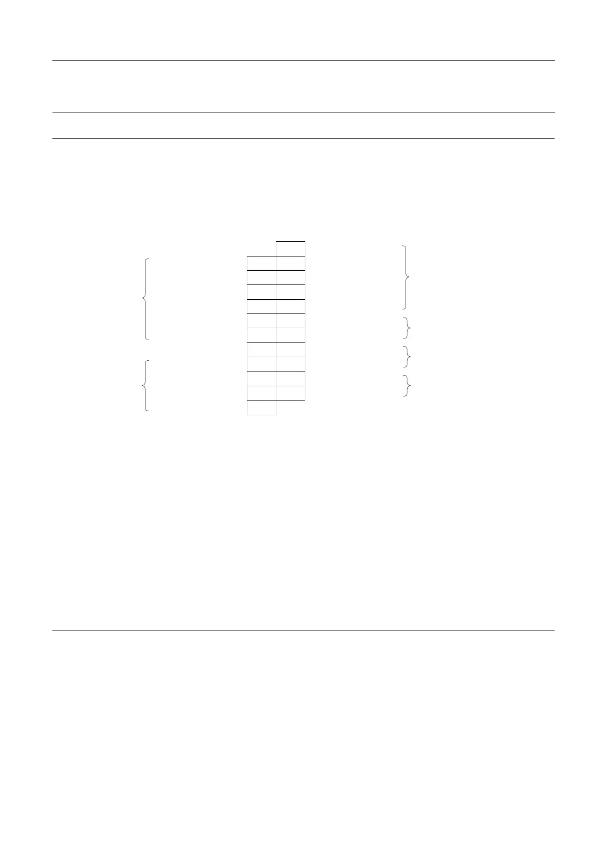
5.7Electricalconnection,internal-DeviceNet
Electrical Electrical
Electrical
connection connection
connection
DeviceNet63node
Sensorboard
Terminalstrip
P2
P1
1
PowerbusV-(Black)
N/C
62
CAN_L(Blue)
N/C
7
3
Drain(Bare)
N/C
8
4
CAN_H(White)
N/C
9
5
PowerbusV+(Red)
Buscable
N/C
1012
N/C
NotConnected
N/C
11
13
N/C
Notconnected
EarthEarth24
Seat-lift1"upper"
Solenoidcom.grey
2025
Seat-lift2"lower"
Incomingsignalsfromexternal
sensors*)
Solenoid1,grey
2126
Supply+
Solenoid2,grey
2227
Supply-
Supplytoexternalsensors*)
Internalconnections
tosolenoids1-3***)
Solenoid3,grey
23
T T
T
able able
able
3. 3.
3.
Note! Note!
Note!
*)Ifusingexternalsensor,thesensormustbeactive/activatedwhenperformingaset-uproutineofthecontrolhead.
Terminals24,25,26and27canbeusedforexternalseatliftsensorsaswellasforanydigitalinput.Alwaysuseanexternal
PNPsensor.Twoexternalsignalscanbeconnected;theseareassociatedwithfeedbacksignal3(seat-lift1)and4(seat-lift
2).Externalsensormustalwaysbea8-30VDCPNP3wiresensor.Connect(-)commononterminal27and(+)common
onterminal26.Thesignalsfromtheexternalsensorsareassociatedasfollows:sensorsignalonterminal24(seat-lift1)
associatedwithfeedback3(seat-lift1)andsensorsignalonterminal25(seat-lift2)associatedwithfeedback4(seat-lift2).
***)
Internalconnections:Terminalsforconnectionforthesolenoidsmountedinternallyinthecontrolhead.Thenumberof
solenoidsactuallymountedinthecontrolheadcouldbe0-3.Thesignalsaretakendirectlyfromtheterminalrow.
Note! Note!
Note!
Remembertoisolatewiresthatarenotinuse.
24