Removing and installing components
NOTE: The images in this document may differ from your computer depending on the configuration you ordered.
Recommended tools
The procedures in this document may require the following tools:
● Phillips screwdriver #0
● Plastic scribe
Screw list
NOTE: When removing screws from a component, it is recommended to note the screw type, the quantity of screws, and then
place them in a screw storage box. This is to ensure that the correct number of screws and correct screw type is restored when
the component is replaced.
NOTE: Some computers have magnetic surfaces. Ensure that the screws are not left attached to such surfaces when replacing a
component.
NOTE: Screw color may vary with the configuration ordered.
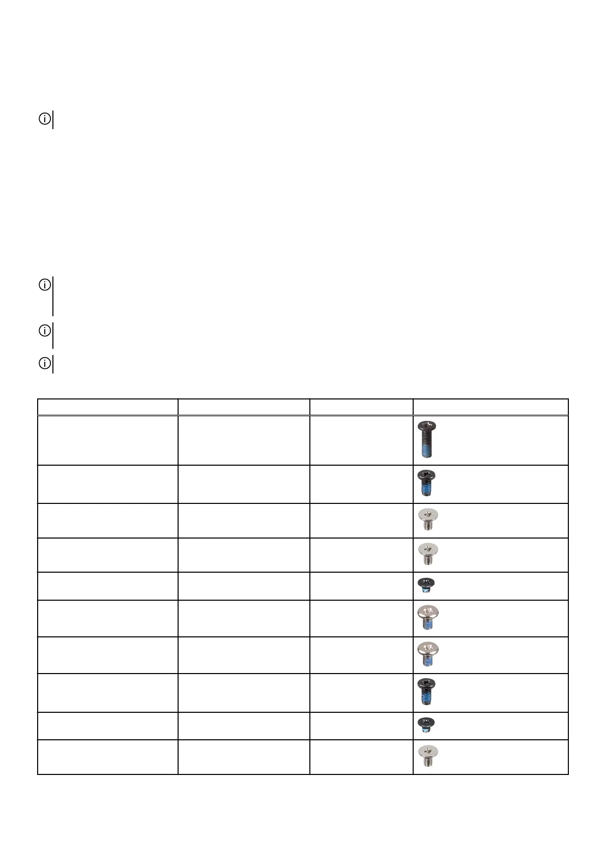
Table 1. Screw list
Component Screw type Quantity Screw image
Base cover M2.5x8 (captive screw) 2
Base cover M2.5x5 6
2280 or 2230 solid-state drive
in SSD Slot one and two
M2x3.5 2
2230 solid-state drive in SSD
Slot three and four
M2x3.5 2
Wireless-card bracket M2x2.5 2
Small fan M2x4 3
Rear I/O cover M2x4 5
Rear I/O cover M2.5x5 2
I/O board M2x2.5 4
Battery M2x3.5 4
9