20 Rockwell Automation Publication 1420-UM001E-EN-P - March 2016
Chapter 2 Installation and Wiring
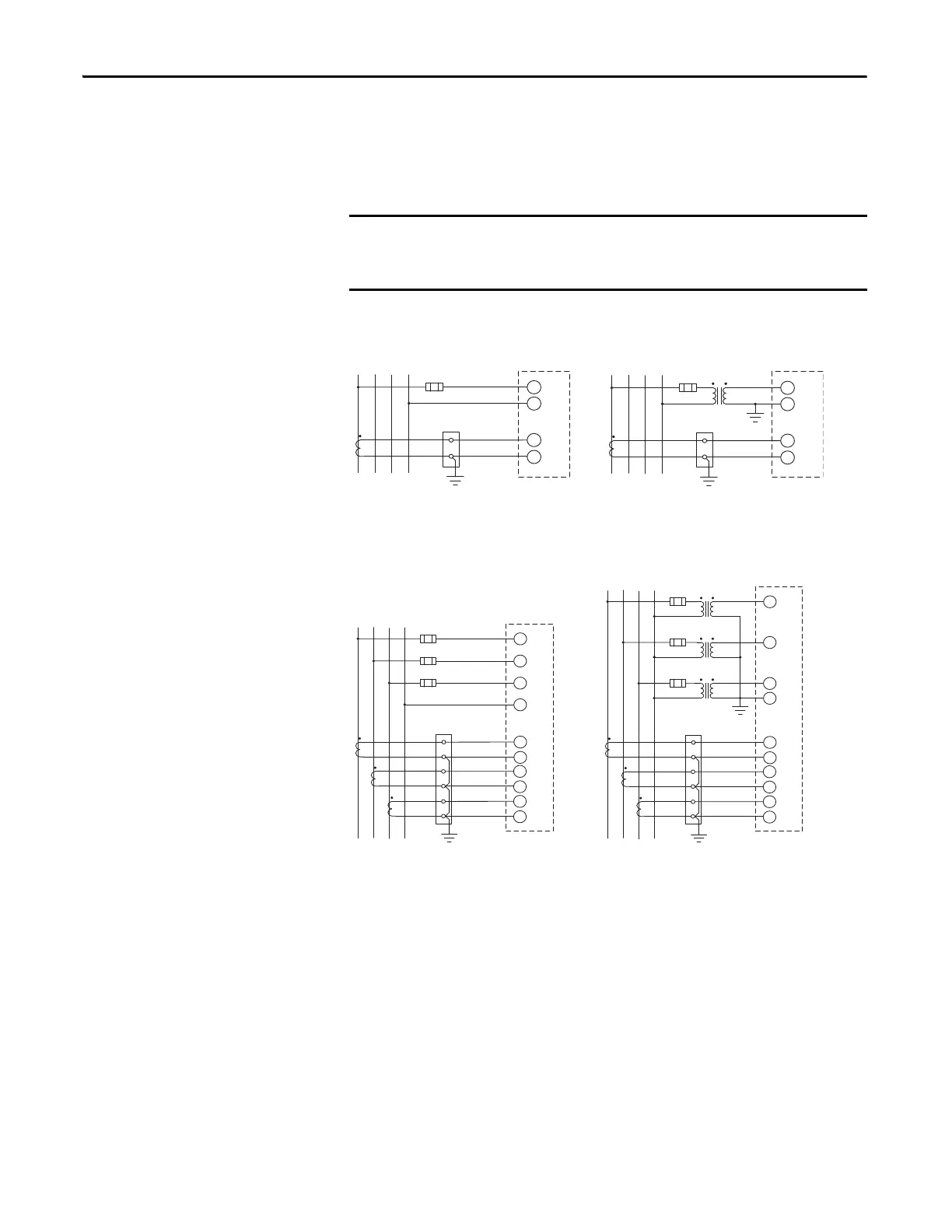
These diagrams are simplified. Wiring of the power monitor must comply with
all applicable codes, standards, and regulations. Protect voltage and control
power wiring with suitable overcurrent protection. Connect current transformer
(CT) secondary wiring through a suitable shorting terminal block.
Figure 11 - 3-phase, 2-wire Wye, Balanced Load
Figure 12 - 3-phase, 4-wire Wye, Unbalanced Load
In these diagrams, ‘balanced load’ configurations permit 3-phase
measurement by using only one phase connection. Unbalance in the measured
circuit affects the accuracy of the measurements.
Line
L1 N
Fuse
PT
(VT )
Load
Ground
Shorting
terminal block
S1
I1
Ground
CT
1
L2
L3
L1
S2
N
Line
L1 N
Fuse
Load
Ground
Shorting
terminal block
S1
I1
CT
1
L2
L3
L1
S2
N
PM 500 PM 500
1-CT Connection
1-CT and 1-PT/VT Connections
Meter Configuration: System = 3P.2
Line
L1 N
Fuse
PT 1
(VT 1)
Load
Ground
Sh ort ing
terminal block
S1
I1
Ground
CT
1
L2
L3
L1
S2
PM 500
3-CT and 3-PT/VT Connections
S1
I2
CT
2
S2
S1
I3
CT
3
S2
Fuse
PT 2
(VT 2)
L2
Fuse
PT 3
(VT 3)
L3
N
Line
L1 N
Fuse
Load
Ground
Shorting
terminal block
S1
I1
CT
1
L2
L3
L1
S2
PM 500
3-CT Connection
S1
I2
CT
2
S2
S1
I3
CT
3
S2
Fuse
L2
Fuse
L3
N
Meter Configuration: System = 3P.n
 Loading...


