Rockwell Automation Publication 1420-UM001E-EN-P - March 2016 13
PowerMonitor 500 Unit Overview Chapter 1
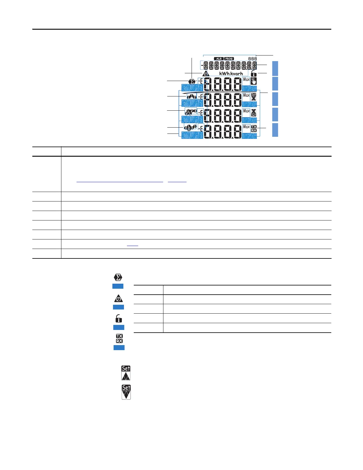
Display Features
Figure 2 - Features
Display Icons
Alarm Icons
• Indicates a high value alarm
• Indicates a low value alarm
ROW 1ROW 2ROW 3ROW 4ROW 5
Display Item Description
1 Phase displacement indicator: inductive L, -L, or capacitive C, -C.
The sign is based on the direction of real power flow.
Positive = consuming power, negative = generating power.
See the Geometric Representation of Power and Power Factor
in Appendix A for more information.
In Programming mode, the indicator displays E when a parameter can be edited.
2 Indicates the measured value phase (line-to-neutral L1 or line-to-line L12).
3 Indicates the measured value phase (line-to-neutral L2 or line-to-line L23).
4 Indicates the measured value phase (line-to-neutral L3 or line-to-line L31).
5 Engineering unit and multiplier indicator (k, M, V, W, A, var, PF, Hz, An).
6 ALR: the alarm display function is active. PROG: the programming function is active.
7 Area set aside for energy counters (see Tab le 1
), text messages, date and time (format: dd.mm.yy/hh:mm).
8 Indicates that metering values are dmd (demand) or MAX (maximum) values.
Display Item Description
9 Indicates that the metering values displayed are system (three-phase) values.
10 Indicates a phase sequence error alarm for Voltage rotation.
11 Configuration lock switch is not active. Always indicates unlocked.
12 Indication of serial RS-485/RS-232 data transmission (TX) and reception (RX).
 Loading...


