22 Rockwell Automation Publication 1420-UM001E-EN-P - March 2016
Chapter 2 Installation and Wiring
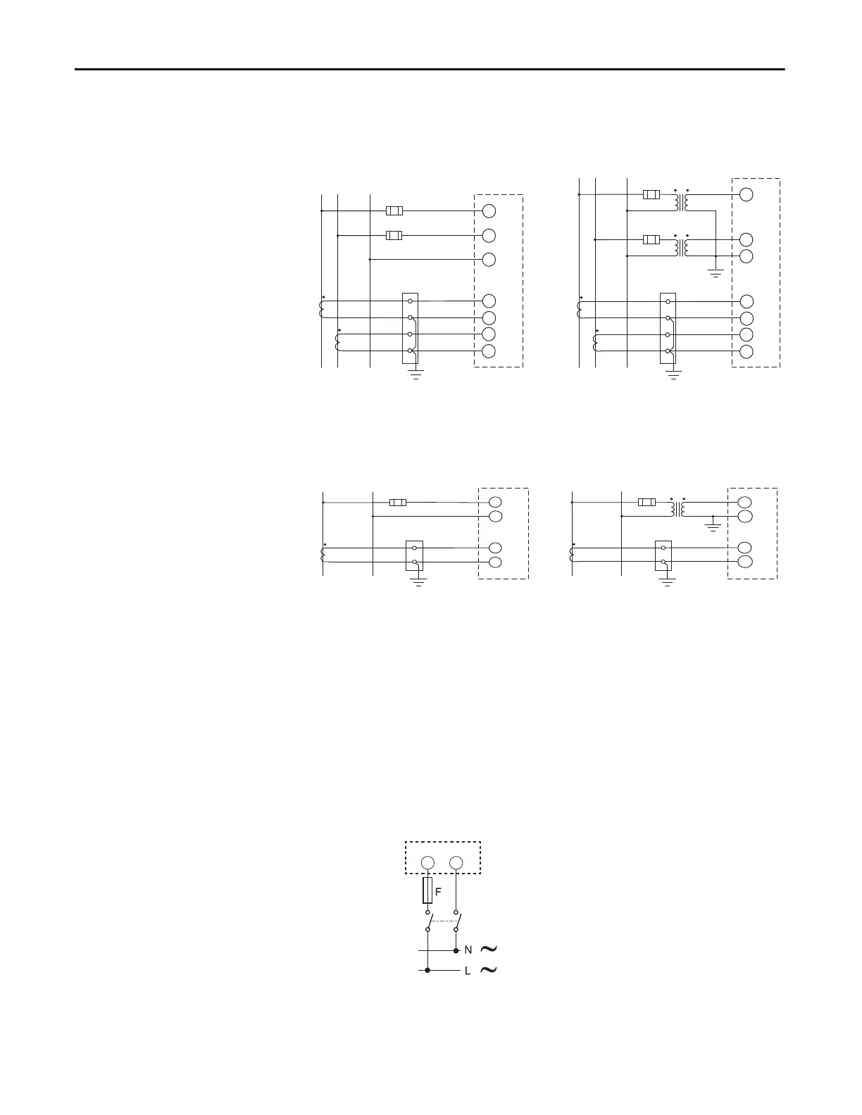
Figure 15 - Split-phase
Figure 16 - Single-phase
Supply Power
Connect the PowerMonitor™ 500 unit to a source of supply power through user-
provided disconnecting means, such as a switch or circuit breaker close to the
power monitor. Provide overcurrent protection that is sized to protect the wiring.
Apply supply power only after all wiring connections are made to the unit.
Figure 17 - Supply Power
Line
L1 N
Fuse
PT 1
(VT 1)
Ground
L2
L1
PM 500
2-CT and 2-PT/VT Connections
Fuse
PT 2
(VT 2)
L2
Line
L1 N
Fuse
Load
Ground
Shorting
terminal block
S1
I1
CT
1
L2
L1
S2
PM 500
2-CT Connection
S1
I2
CT
2
S2
Fuse
L2
N
Load
Ground
Shorting
terminal block
S1
I1
CT
1
S2
S1
I2
CT
2
S2
N
Meter Configuration: System = 2P
Line
L1 N
Fuse
PT
(VT )
Load
Ground
Shorting
terminal block
L1
N
S1
S2
I1
Ground
CT
Line
L1 N
Fuse
Load
Ground
Shorting
terminal block
L1
N
S1
S2
I1
CT
PM 500 PM 500
1-CT Connection
1-CT and 1-PT/VT Connections
Meter Configuration: System = 1P
120/240V AC 50/60Hz, or 120/240V DC
PowerMonitor 500
F = 250V (T) 630 mA
2
1
+
+
-
-
 Loading...


