104 Rockwell Automation Publication 1734-UM013N-EN-P - September 2017
Chapter 5 Configure the Module in a GuardLogix Controller System
To configure alarms for each of the safety analog input channels, follow these
steps.
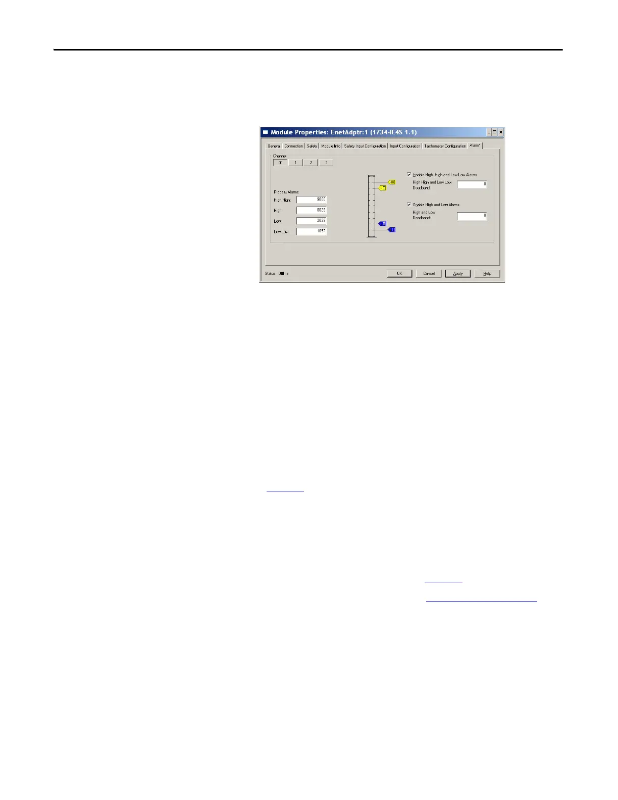
1. From the Module Properties dialog box, click the Alarm tab.
2. To configure each channel, click 0, 1, 2, or 3, as appropriate.
3. To enable the alarm, check the boxes:
• Enable High High - Low Low Alarms
• Enable High - Low Alarms
4. Type the alarm values from -32768…32767 in the appropriate fields,
following these guidelines:
• The High High alarm value must be greater than or equal to the High
alarm value.
• The High alarm value must be greater that the Low alarm value.
• The Low Low alarm value must be less than or equal to the Low alarm
value.
• These values are based on the engineering units that are configured on
page 103
.
5. Configure a deadband value for the High High - Low Low alarms and
High - Low alarms, if desired.
The valid range is 0…32767. The deadband lets the alarm status bit remain
set, despite the alarm condition disappearing, as long as the input data
remains within the deadband of the alarm. These values are based on the
Engineering units that are configured on page 103
.
For more information on this feature, see Process Alarms
on page 35
 Loading...


