Rockwell Automation Publication 1734-UM013N-EN-P - September 2017 63
Install the Module Chapter 4
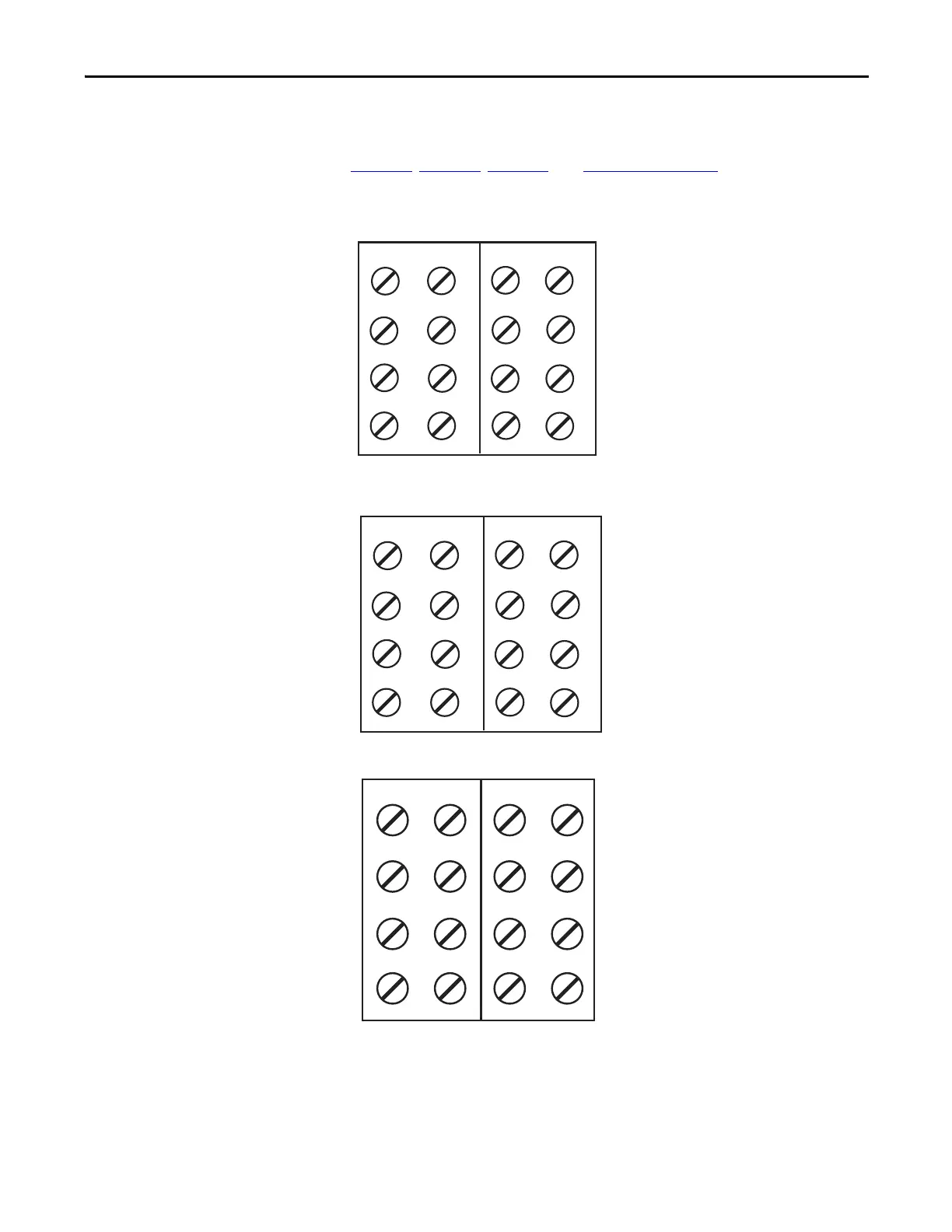
Terminal Layout
Figure 26, Figure 27, Figure 28, and Figure 29 on page 64 show the field wiring
connections for the POINT Guard I/O modules.
Figure 26 - 1734-IB8S Field Connections
Figure 27 - 1734-OB8S Field Connections
Figure 28 - 1734-OBV2S Field Connections
Where:
T0 = Test Output 0
T1M = Test Output 1 with Muting
T2 = Test Output 2
T3M = Test Output 3 with Muting
I0…I7 = Inputs 0…7
COM = Supply Common
1734-TOP and 1734-TB Bases Shown
T0
COM
COM
COM
COM
T1M
T2
T3M
I0
I1
I4
I5
I2
I3
I6
I7
1
3
0
2
4
5
6
7
1
3
5
7
0
2
4
6
1734-TOP and 1734-TB Bases Shown
Where:
O0…O7 = Safety Outputs 0…7
COM = Supply Common
COM
COM
COM
COM
O0
O1
O4
O5
O2
O3
O6
O7
1
3
0
2
4
5
6
7
1
3
5
7
0
2
4
6
COM
COM
COM
COM
1734-TOP and 1734-TB Bases Shown
Where:
Channels O0 and O1 = safety output bipolar pair
Channels O2 and O3 = safety output bipolar pair
Channels O0 and O2 = sourcing outputs
Channels O1 and O3 = sinking outputs
COM = Sensor Power supply common
V = Sensor Power supply
V
COM
COM
COM
COM
V
VV
O0
O1
O2 O3
O0
O1
O2
O3
 Loading...


