Rockwell Automation Publication 1734-UM013N-EN-P - September 2017 157
Replacing POINT Guard I/O Modules Chapter 8
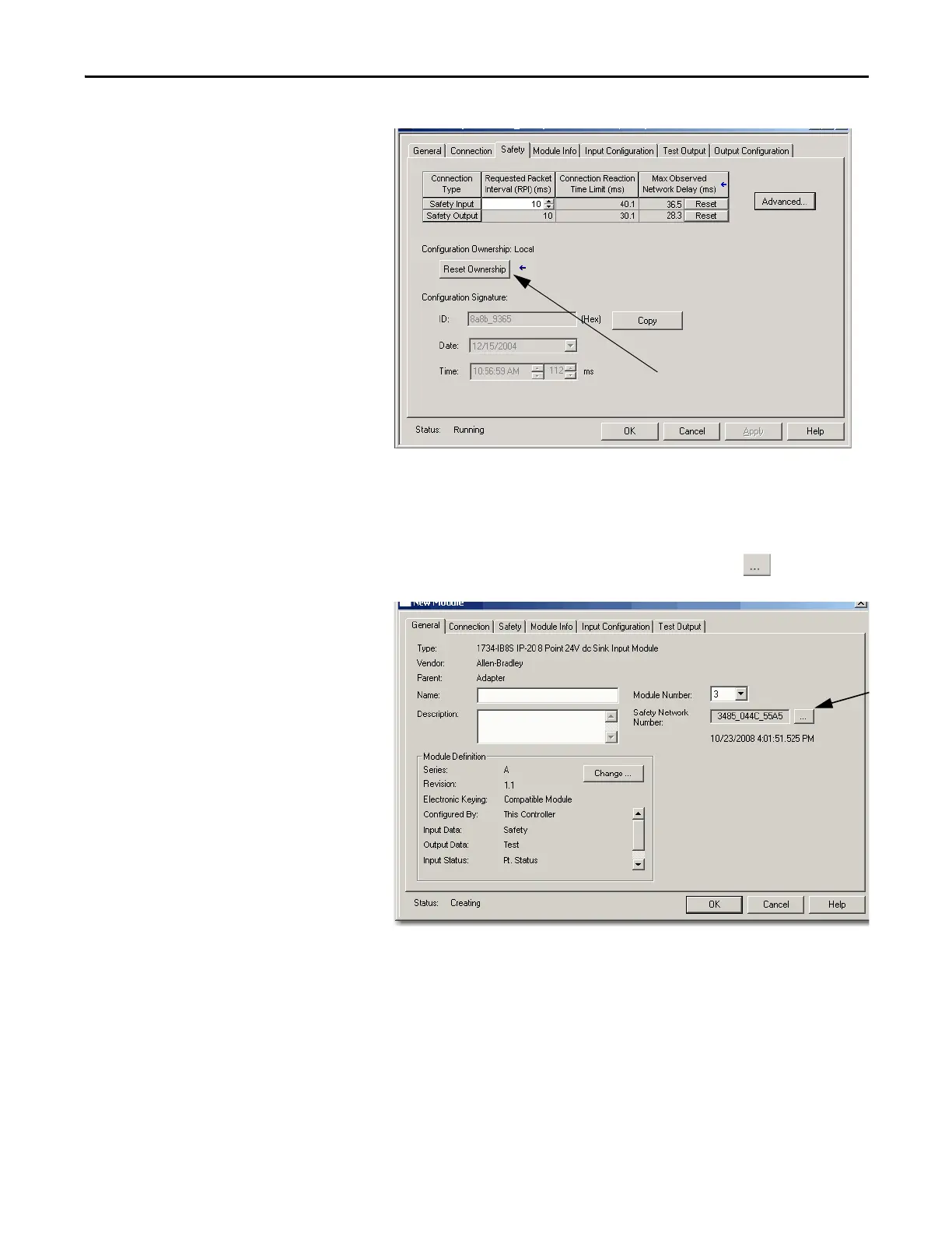
3. Click the Safety tab.
4. Click Reset Ownership.
5. Click OK.
6. Right-click your module and choose Properties.
7. To open the Safety Network Number dialog box, click to the right of
the safety network number.
 Loading...


