Rockwell Automation Publication 1734-UM013N-EN-P - September 2017 195
Specifications Appendix C
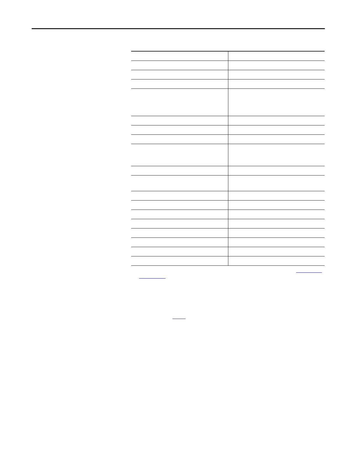
Power dissipation, max
(2)
3.1 W
Thermal dissipation, max 10.59 BTU/hr
Power dissipation, typical
(3)
2.2 W
Isolation voltage 50V (continuous), Basic Insulation Type between field
side and system
No isolation between individual channels
Type tested at 500V AC for 60 s channel to channel.
Power bus, operating supply voltage 24V DC nom, SELV, 150 VA max
Power bus, operating voltage range 19.2…28.8V DC, SELV, 150 VA max
Power bus current (no load), max 65 mA
Indicators 1 yellow lock status indicator
1 green/yellow power status indicator
4 I/O channel status indicators
Keyswitch positions (left and right) Key 1 = 8 (left); Key 2 = 2 (right)
Pilot duty rating DC-13, DC-14
Inrush Electronically limited 1.8A
North America temp code T4
ATEX temp code T4
Enclosure type rating None (open-style)
Wiring category
(4)
2 - on signal ports
Wire size Determined by installed terminal block
Terminal block torque Determined by installed terminal block
Weight, approx. 62.4 g (2.2 oz)
Dimensions (HxWxD), approx. (without terminal block) 77 x 25 x 55 mm (3.03 x 0.98 x 2.17 in.)
(1) To comply with UL certification requirements, power must be supplied from SELV compliant power supply (See Choosing a Power
Supply on page 47) which limits available field power to 150 VA. Therefore, the aggregate current of outputs per module is limited
to a maximum set by the 150 VA limit (unless derated further as shown) for applications that require UL listing.
(2) Maximum power dissipation applies when using 28.8V DC module supply and maximum power dissipated with all four outputs in
the ON state.
(3) Typical power dissipation applies when using 24V DC module supply and nominal power dissipated with all four outputs in the ON
state.
(4) Use this conductor category information for planning conductor routing. See the Industrial Automation Wiring and Grounding
Guidelines, publication 1770-4.1
.
Table 20 - Safety Digital Output Module Specifications 1734-OBV2S (continued)
Attribute Value
 Loading...


