Publication 1746-5.16
13
Outputs
The module provides four physical outputs. They can be controlled by the
module when certain counter conditions are met, or they can be controlled from
the user program (refer to High-Speed Counter Module User Manual, publication
1746-6.5 for M0:e.0 information).
The outputs are bipolar transistors connected in a sinking (open collector sinking)
configuration. When the output is energized, it sinks the current.
1
2
3
4
5
6
7
0
A
B
Z
LS
OUTPUT INPUT
FAULT
HSCE
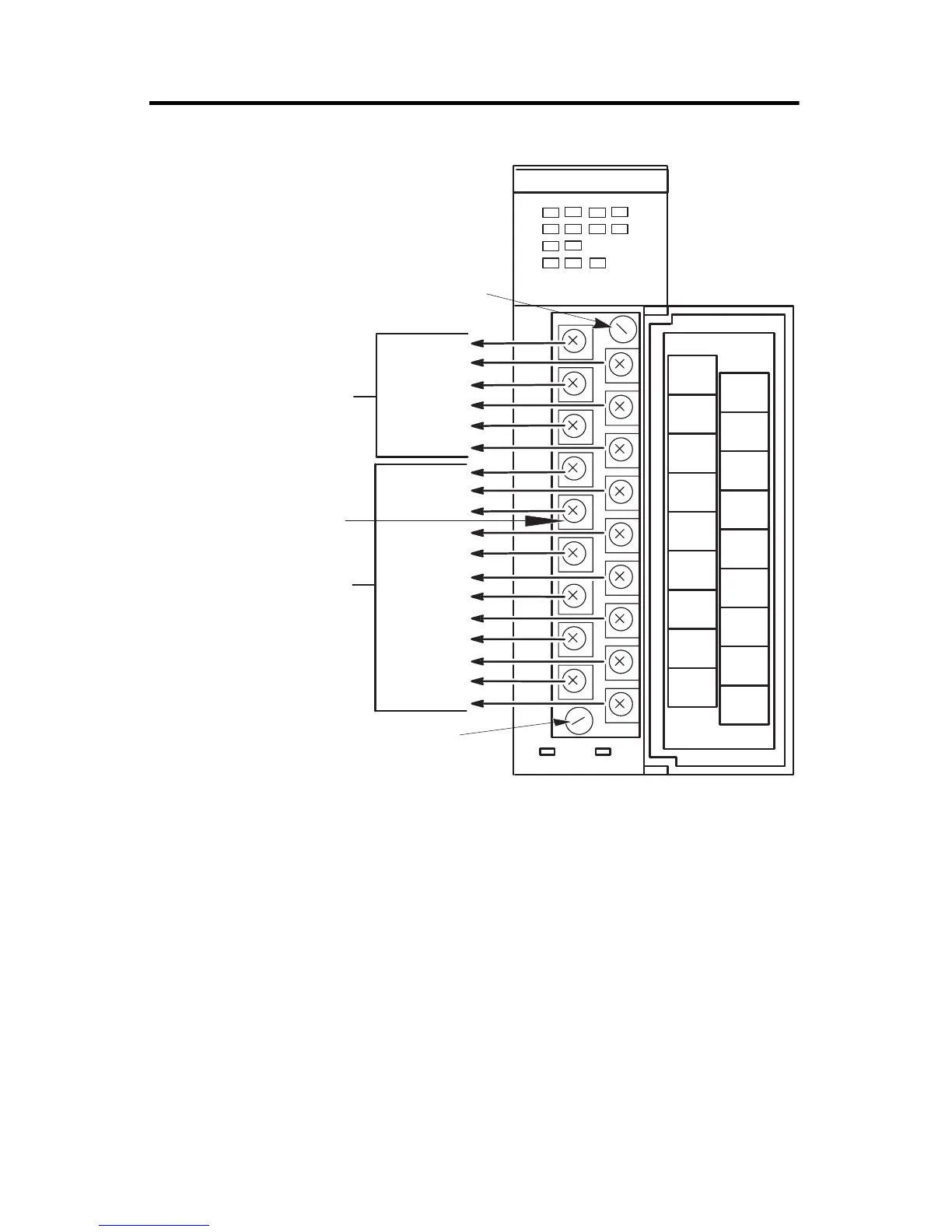
Upper Retaining Screw Maximum
Torque = 0.7-0.9 Nm (6-8 in-lbs)
VDC
OUT 1
OUT 3
A+
A-
Not
Used
Z+
Z-
LS
COM
OUT 0
OUT 2
DC
COM
B+
B-
Not
Used
LS
(24V dc)
LS
12V dc)
LS
(5V dc)
Lower Retaining Screw Maximum
Torque = 0.7-0.9 Nm (6-8 in-lbs)
Discrete Output Wiring
NOTE: VDC must be externally
supplied by the user. See page
14 for output wiring.
Terminal Wiring
-max. #14 AWG (2mm
2
)
max. 2 wires per terminal
max. torque: 0.9 Nm (8 in-lbs)
Limit Switch and Encoder
Input Wiring
See pages 14 through 20 for
input wiring.
VDC
OUT 0
OUT 1
OUT 2
OUT 3
DC COM
A+
B+
A-
B-
Not used
Not used
Z+
LS (24VDC)
Z-
LS (12VDC)
LS COM
LS (5VDC)
Allen-Bradley HMIs

 Loading...


