14
Publication 1746-5.16
You can select an output voltage range of 4.5-10V dc or 10-30V dc. Refer to page
22 for the maximum current specifications for each voltage range. Dip switch
SW2, located on the PC board, is used to select the voltage range. Refer to pages
7 through 9 for switch SW2 location and settings.
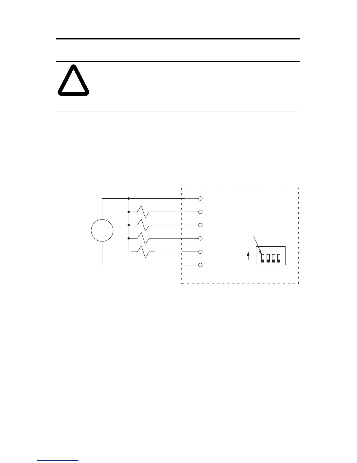
The figure below indicates wiring connections for four 24V dc outputs. Switches
of SW2 are OFF for this output voltage.
The outputs are not electrically isolated from each other. (They are referenced to
the same output common terminal.) However, outputs are isolated from the rest
of the circuitry to a level of 1500 volts.
Encoders
The wiring diagrams on the following pages are provided to support the
Allen-Bradley encoders you may already have. Differential encoders provide the
best immunity to electrical noise. We recommend, whenever possible, to use
differential encoders.
!
ATTENTION: Do not use incandescent lamps as output
indicators. The high peak inrush current required to heat the
filament can damage the module’s output circuits. Use LED type
indicators that satisfy the output circuit ratings, such as
Allen-Bradley 800A and 800T LED indicators.
+
±
1234
User Supplied
24V dc
wiring terminals
VDC
OUT 0
OUT 1
OUT 2
OUT 3
DC COM
All switches OFF
ON
OFF
Dip Switch SW2
HSCE module

 Loading...


