Publication 1746-5.16
15
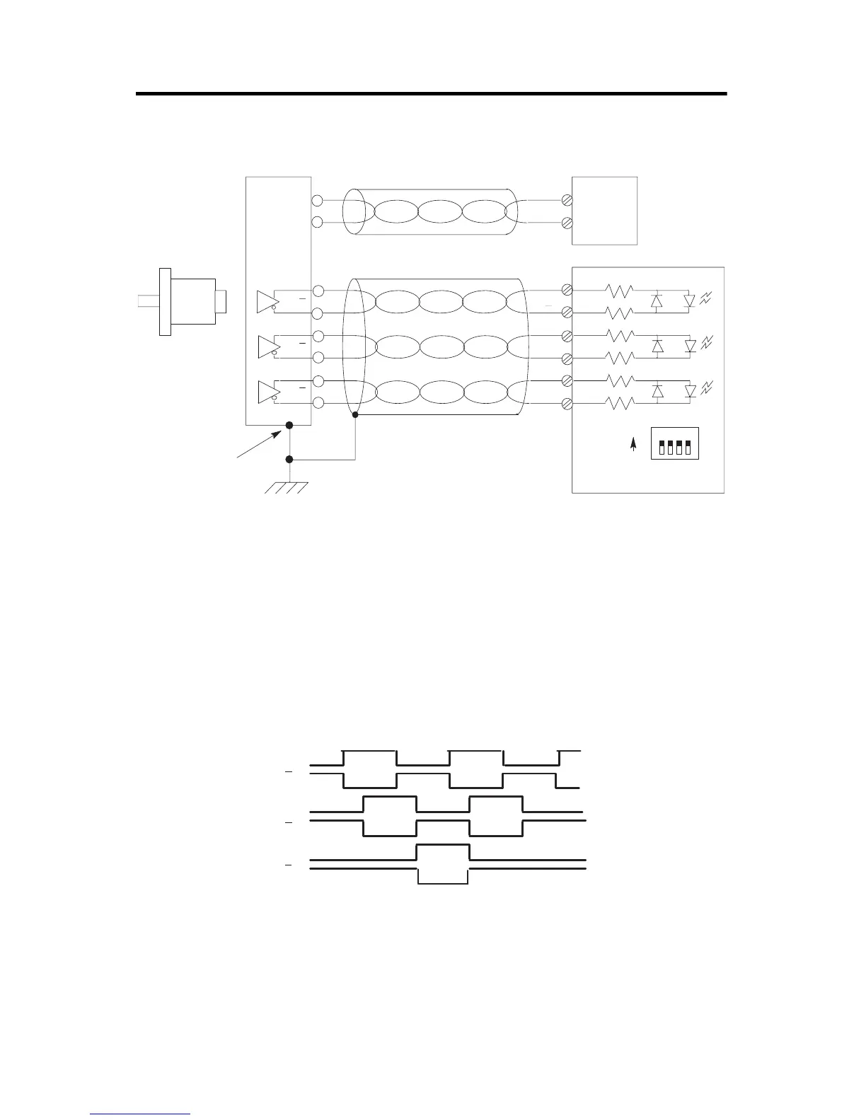
Differential Encoder Wiring
A
A
B
B
Z
Z
A(+)
A(±)
B(+)
B(±)
Z(+)
Z(±)
1234
cable
1
Belden 9503 or equivalent
305m (1000ft) max length
Power
Supply
+ VDC
COM
VS
GND
Allen-Bradley
845H Series
differential
encoder
encoder connector
housing
Earth
Shield
(2)
Module Inputs
SW1
ON
OFF
(all switches ON)
(1) Refer to your encoder manual for proper cable type and length.
(2) Due to the topology of the module’s input circuits, terminating the shield at the encoder end
provides the highest immunity to EMI interference. Connect EARTH ground directly to the
encoder connector housing.
A
A
B
B
Z
Z
The illustration below shows the different encoder output waveforms. If your encoder matches these
waveforms, the encoder signals can be directly connected to the associated screw terminals on the
module. For example, the A lead from the encoder is connected to the module’s A+ screw. If your
encoder does not match these waveforms, some wiring modifications may be necessary. Refer to
appendix C in
High-Speed Counter Module User Manual
, publication 1746-6.5 for a description of
these modifications.
Differential Encoder Output Waveforms
Allen-Bradley HMIs

 Loading...


