Publication 1769-UM009B-EN-P - May 2002
8-2 Troubleshooting
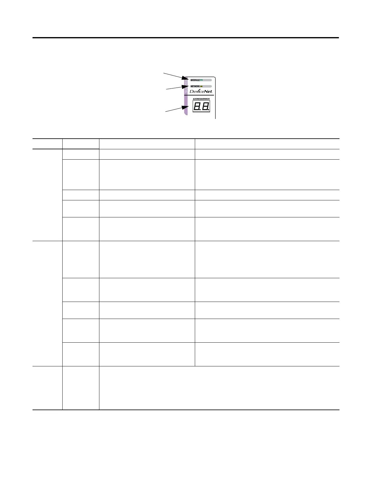
The following table summarizes the meanings of the LEDs and
numeric codes.
Module LED
Network LED
Node Address and
Status Display
Table 8.1 Troubleshooting the LEDs and Numeric Display
Indicator Color/Status Indicates Recommended Action
Module Off No power applied to module. Apply power.
Flashing
Green
No Bus Master (MicroLogix or
CompactLogix controller) present.
Verify module connectors are properly seated. If they are, cycle
power to the controller. If this does not correct the problem,
replace the controller. If replacing the controller does not
correct the problem, replace the scanner.
Solid Green Normal operation. No action required.
Flashing Red Recoverable Fault - Memory has been
erased or is being programmed.
Complete flash update or start a new update.
Solid Red Unrecoverable fault Verify module connectors are properly seated. If they are, verify
that bus terminator/end cap is installed. Cycle power. If still
faulted, replace the module.
Network Off No module power, no network power, or
communications are not occurring
between the module and the DeviceNet
network. (This may be an acceptable
condition.)
Verify module has power. Check that the DeviceNet cable is
securely connected and the DeviceNet network is powered.
Verify that network power is adequate (11 to 25V dc).
Flashing
Green
Device is operational. There are no
connections established with any of the
network devices.
If the module is supposed to be controlling DeviceNet slaves,
configure the module’s scanlist.
Solid Green Normal operation. Scanlist is configured.
Module is not in Idle mode.
No action required.
Flashing Red One or more of the devices that the
scanner is communicating with is in a
timed out state.
Monitor the status display, or the module’s status field to
determine which slave device is offline.
Solid Red Critical network failure. Duplicate
DeviceNet node address detected.
Reset module. Change module’s node address or change
conflicting device’s node address. If failure continues, replace
module.
7-Segment
Numeric
Display
Node Address
and Status
Display
Indicates diagnostic information about the status of the module.
• When the numeric display is showing 0 to 63, it is indicating the scanner’s DeviceNet node address.
• When it shows 70 to 99, it indicates an Error Code for the displayed node address.
• When it flashes alternating numbers, one is the Error Code (70 to 99), and the other is the Node
Number (0 to 63) that has generated the error.
See the list of Error Codes on page 8-3 for more information.

 Loading...


