Publication 1769-UM009B-EN-P - May 2002
Using the 1769-SDN Scanner Module with CompactLogix Controllers 6-9
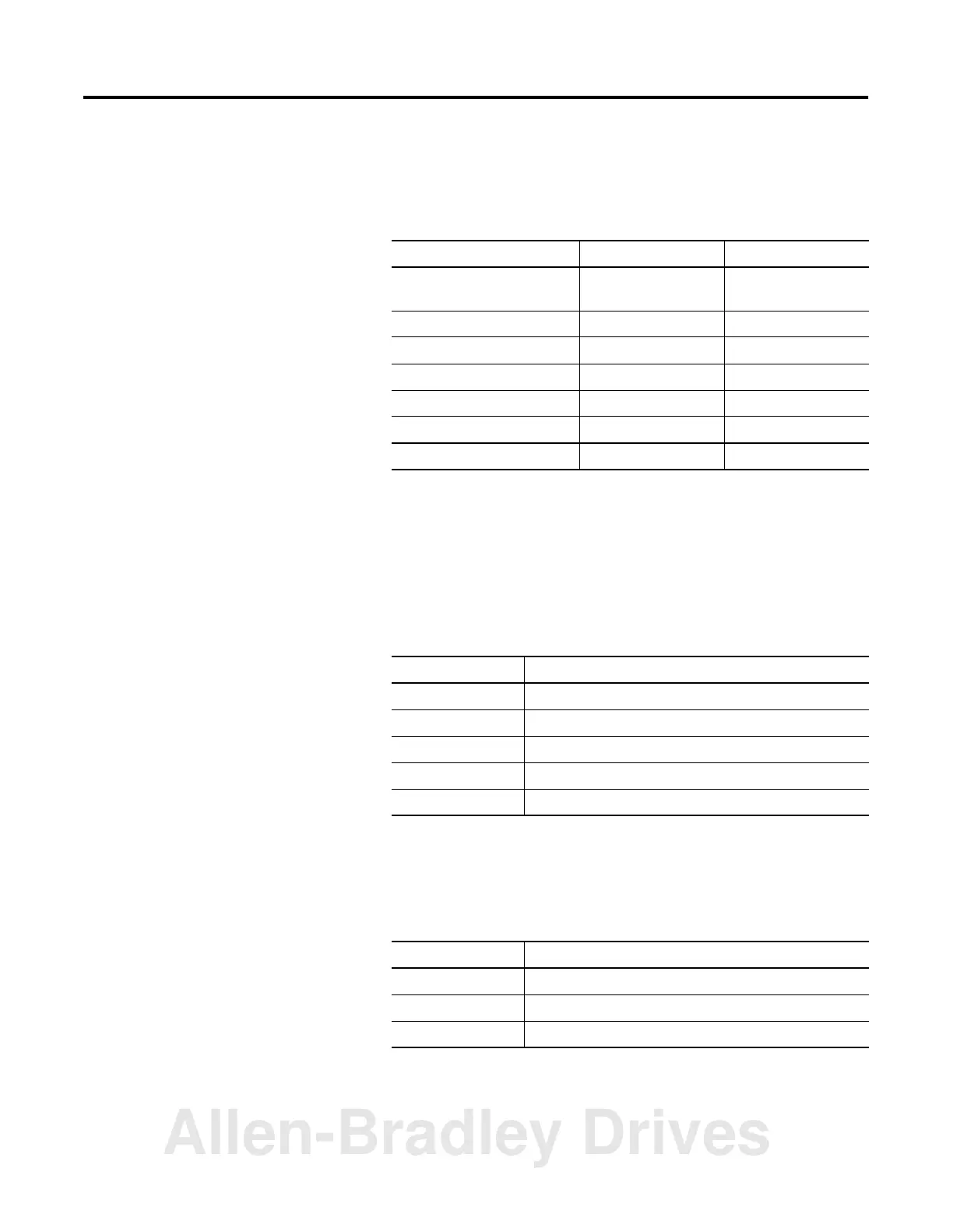
For example, there are 28 bytes of input data and 6 bytes of
output data for this example. The I/O modules in the adapter’s
system are:
The total is 14 input words or 28 input bytes. The first two input
words are adapter status, leaving 12 words (24 bytes) for data. In
this example, words 66 and 67 are the two words of status in the
controller input tag for the scanner. The actual input data is then
mapped to the controller’s input data tag at the following word
locations:
The output data can be determined in a similar manner. This
data begins with word 2 of the output tag in the controller for
the scanner as follows:
Table 6.1 1769-ADN I/O Bank Input and Output Data Size
Module Input Output
ADN Status Information
(added by the 1769-ADN)
2 words 0 words
1769-IA16 1 word 0 words
1769-OB16 1 word 1 word
1769-IF4 6 words 0 words
1769-OF2 4 words 2 words
Total Words 14 words 3 words
Total Bytes 28 bytes 6 bytes
Table 6.2 Input Data Tag
Location Description
Words 66 and 67 1769-ADN Status Information
Word 68 1769-IA16 module’s input word
Word 69 1769-OB16 module’s input data (output data echo)
Words 70 to 75 1769-IF4 module’s input data
Words 76 to 79 1769-OF2 module’s input data
Table 6.3 Output Data Tag
Location Description
Word 0 and 1 See Module Command Array on page 5-8.
Word 2 1769-OB16 module’s output word
Words 3 and 4 1769-OF2 module’s output words
Allen-Bradley Drives

 Loading...


