10 Rockwell Automation Publication 1783-IN016B-EN-P - March 2019
Stratix 5700 Ethernet Managed Switches
8. Connect the other end of the positive wire to the positive terminal on the DC power source.
9. Connect the other end of the return wire to the return terminal on the DC power source.
When you are testing the switch, one power connection is sufficient. If you are installing the switch and are using a second power source,
repeat this procedure with the second power connector.
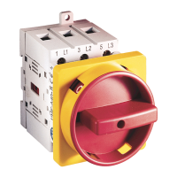
The following figure shows the completed DC input wiring on a power connector for a primary power source and an optional secondary
power source.
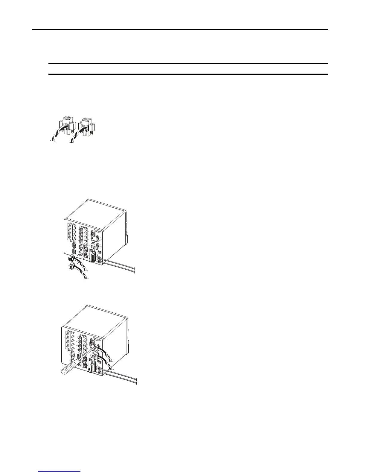
Install the Power Connectors on the Switch
To install the switch power connectors to the front panel of the switch, follow these steps.
1. Insert one power connector into the Pwr A receptacle on the switch front panel, and the other into the Pwr B receptacle.
2. Use a ratcheting torque flathead screwdriver to tighten the captive screws on the sides of the power connectors.
When you test the switch, one power source is sufficient. If you install a second power source, repeat this procedure for the second power
connector (Pwr B).
3. When you install the switch, secure the wires from the power connectors to the rack by using tie wraps.
IMPORTANT On switches that support PoE, do not connect the negative (return) terminal of the DC power source to earth ground.
 Loading...