Rockwell Automation Publication 1783-IN016B-EN-P - March 2019 7
Stratix 5700 Ethernet Managed Switches
Site Requirements
Observe these site requirements:
• Clearance to front and rear panels meets these conditions:
– Front-panel status indicators can be easily read.
– Access to ports is sufficient for unrestricted cabling.
– Front-panel DC power connectors and the alarm relay connector are within reach of the connection to the DC power source.
• To prevent the switch from overheating, observe these minimum clearances:
– Top and bottom: 50.8 mm (2.0 in.)
– Sides: 50.8 mm (2.0 in.)
– Front: 50.8 mm (2.0 in.)
• Temperature surrounding the unit does not exceed 60 °C (140 °F).
• For 10/100 ports and 10/100/1000 ports, the cable length from a switch to an attached device cannot exceed 100 m (328 ft).
• Cabling is away from sources of electrical noise, such as radios, power lines, and fluorescent lighting fixtures.
• For maximum noise immunity, shielded cables must be used on the RJ45 uplink ports (Gi1/1 and Gi1/2) on these switches:
• Connect the unit to only a Class 2 DC power source.
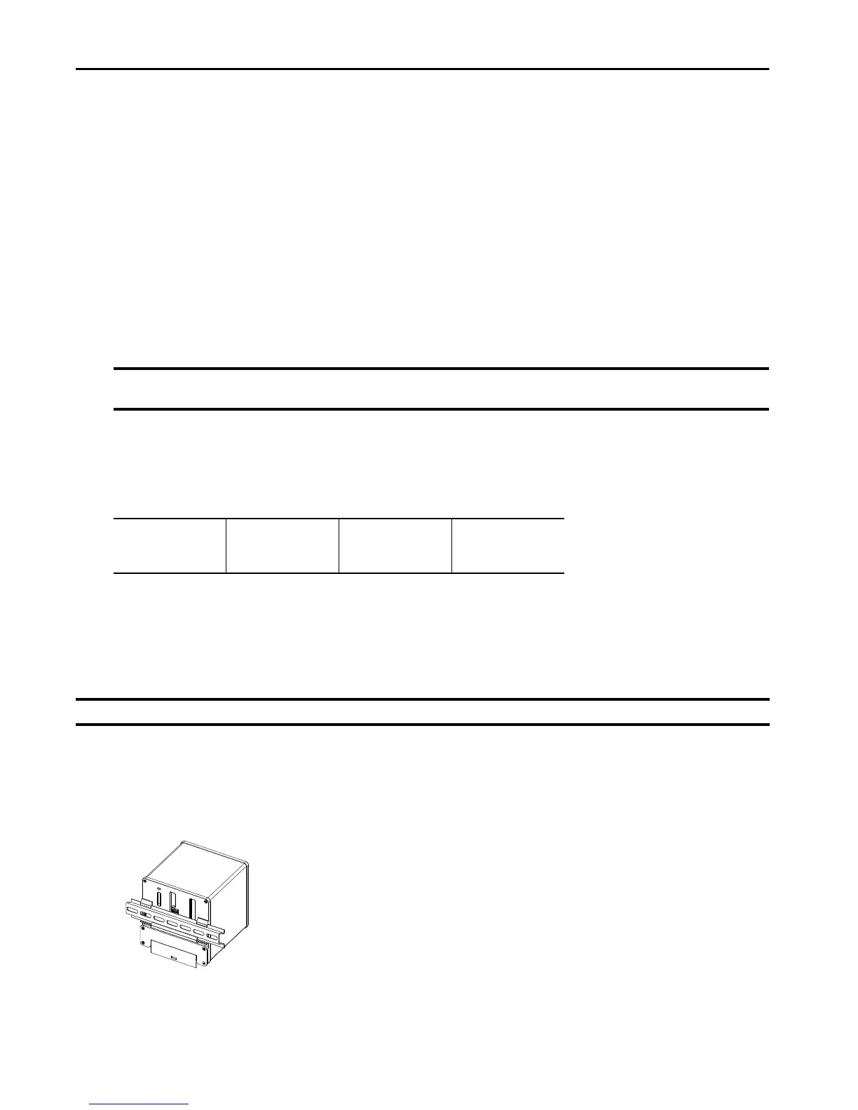
Mount the Switch
The switch ships with a spring-loaded latch on the rear panel for mounting on a DIN rail.
To mount the switch on a DIN rail, follow these steps.
1. Position the rear panel of the switch directly in front of the DIN rail.
Make sure that the DIN rail fits in the space between the two hooks near the top of the switch and the spring-loaded latch near the bottom.
2. Hold the bottom of the switch away from the DIN rail, and place the two hooks on the back of the switch over the top of the DIN rail.
3. Push the switch toward the DIN rail until the spring loaded latch at the bottom rear of the switch moves down and snaps into place.
IMPORTANT When the switch is installed in an industrial enclosure, the temperature within the enclosure is greater than normal room temperature outside the
enclosure. The temperature inside the enclosure cannot exceed 60 °C (140 °F), the maximum ambient enclosure temperature of the switch.
– 1783-BMS06TGL
– 1783-BMS06TGA
– 1783-BMS10CGL
– 1783-BMS10CGA
– 1783-BMS10CGN
– 1783-BMS10CGP
– 1783-BMS12T4E2CGNK
– 1783-BMS12T4E2CGP
– 1783-BMS12T4E2CGL
– 1783-BMS20CGL
– 1783-BMS20CGN
– 1783-BMS20CGP
– 1783-BMS20CGPK
IMPORTANT The switch must be mounted in an upright orientation, as shown in these instructions. Alternative mounting orientations are not supported.
 Loading...