1732E ArmorBlock 2 Port Ethernet Module 9
Publication
1732E-IN004A-EN-E - November 2009
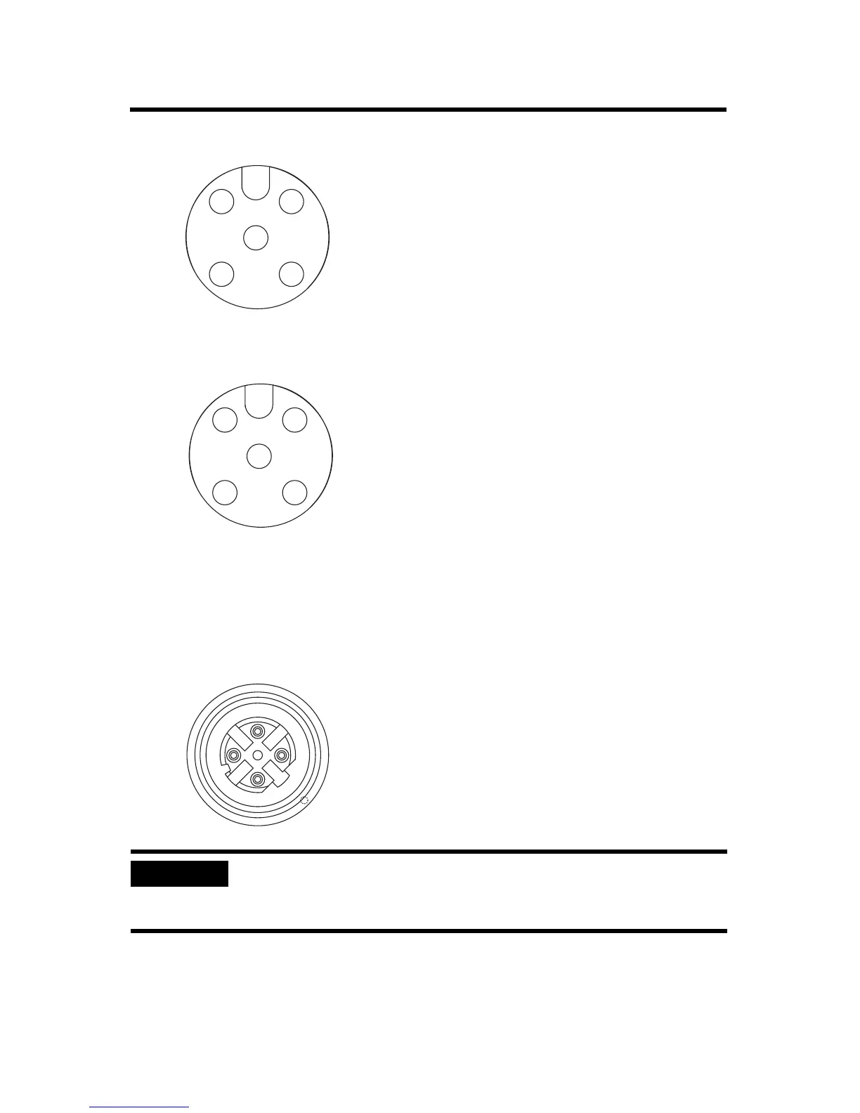
EtherNet/IP Connectors
Refer to the pinout diagrams for the network connectors.
IMPORTANT
Use the 1585D–M4DC–H: Polyamide small body unshielded or the
1585D–M4DC–SH: Zinc die-cast large body shielded mating connectors
for the D-Code M12 female network connector.
1 2
4
5
3
Micro-style 5-Pin Output Female Connector
(View into connector)
Pin 1 Not used
Pin 2 Output B
Pin 3 Return
Pin 4 Output A
Pin 5 PE
44807
1 2
4
5
3
Self-configuring Connector
(View into connector)
Pin 1 Sensor source voltage
Pin 2 Input or output B
Pin 3 Return
Pin 4 Input or output A
Pin 5 PE
44807
4
2
31
5
D-Code M12 Network Female Connector
(View into connector)
Pin 1 M12_Tx+
Pin 2 M12_Rx+
Pin 3 M12_Tx-
Pin 4 M12_Rx-
Pin 5 Connector shell shield FE
44808

 Loading...


