EasyManuals Logo
Home>Allen-Bradley>Controller>CompactLogix 5370 L1

Allen-Bradley CompactLogix 5370 L1 User Manual

Allen-Bradley CompactLogix 5370 L1
327 pages
To Next Page IconTo Next Page
To Previous Page IconTo Previous Page
Page #144 background imageLoading...
Page #144 background image
Rockwell Automation Publication 1769-UM021G-EN-P - October 2015 147
Use I/O Modules with CompactLogix 5370 L1 Controllers Chapter 7
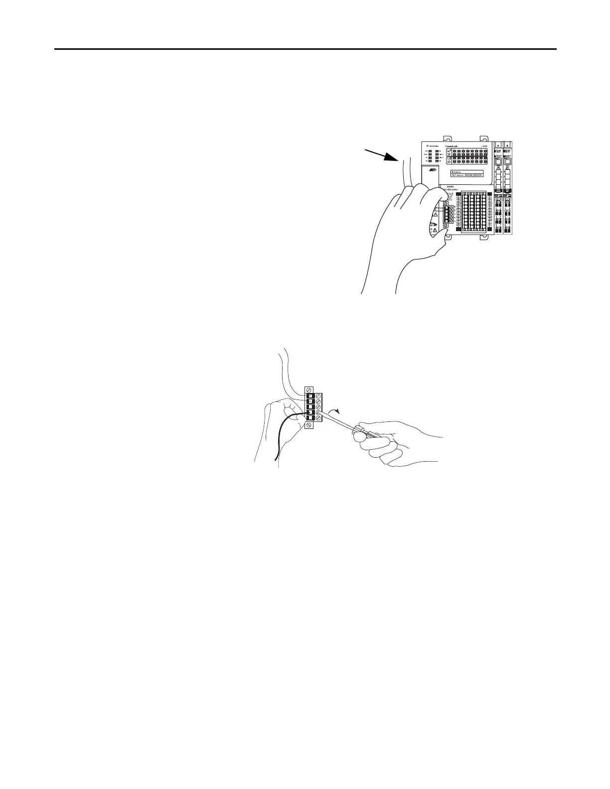
3. Loosen the screws that secure the removable connector to the
CompactLogix 5370 L1 controller and pull the connector off the
controller.
4. Connect the wire that is connected to the + terminal on the external 24V
DC power source to the FP+ terminal, that is, the fourth terminal from
the top, on the removable connector.
Wires that are connected between external
24V DC power source and VDC+ and VDC-
terminals on the removable connector.

Table of Contents

Other manuals for Allen-Bradley CompactLogix 5370 L1

Questions and Answers:

Question and Answer IconNeed help?

Do you have a question about the Allen-Bradley CompactLogix 5370 L1 and is the answer not in the manual?

Allen-Bradley CompactLogix 5370 L1 Specifications

General IconGeneral
BrandAllen-Bradley
ModelCompactLogix 5370 L1
CategoryController
LanguageEnglish

Related product manuals