Rockwell Automation Publication 1769-UM021G-EN-P - October 2015 213
Use I/O Modules with CompactLogix 5370 L2 Controllers Chapter 8
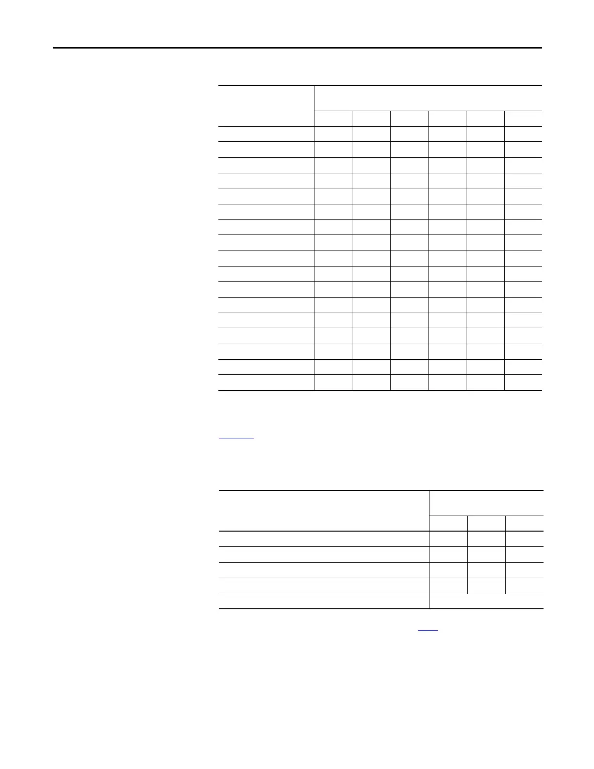
Analog Output Data Format
Tab le 22 lists the bit value combinations you can use to select the output data
format for analog data that is sent to the controller for a channel.
You use bits 8…10
in words 29 and 37 to make this selection.
Thermocouple C 010000
100 Ω PT 385 010001
200 Ω PT 385 010010
500 Ω PT 385 010011
1000 Ω PT 385 010100
100 Ω PT 3916 010101
200 Ω PT 3916 010110
500 Ω PT 3916 010111
1000 Ω PT 3916 011000
10 Ω CU 426 011001
120 Ω Ni 618 011010
120 Ω Ni 672 011011
604 Ω NiFe 518 011100
150 Ω 011101
500 Ω 011110
1000 Ω 011111
3000 Ω 100000
Table 22 - Analog Output Data Format
Analog Output Data Format
Bit Settings
(Words 29 and 37)
Bit 10 Bit 09 Bit 08
Raw/Proportional Data
000
Engineering Units 0 0 1
Scaled for PID 0 1 0
Percent Range 0 1 1
Spare
(1)
(1) An attempt to write a non-valid (any Spare value) bit configuration into the Input/Output Data Format Select field causes a Module
Configuration Error (contained in Mod_Condition Array). All bits shown as 0 in Tabl e 22
are set to 0
Values 4…7
Table 21 - Analog Input Type and Operating Range
Input Type and Normal
Operating Range
Bit Settings
(Words 3, 9, 15, and 21)
Bit 05 Bit 04 Bit 03 Bit 02 Bit Bit 00

 Loading...


